How to Use arduino nano: Examples, Pinouts, and Specs
Introduction
The Arduino Nano is a compact microcontroller board developed by Arduino, based on the ATmega328P microcontroller. It is designed for small-scale projects and prototyping, offering a versatile platform for both beginners and experienced developers. The Nano is equipped with digital and analog input/output pins, USB connectivity, and full compatibility with the Arduino IDE, making it an excellent choice for embedded systems, IoT applications, and robotics.
Explore Projects Built with arduino nano

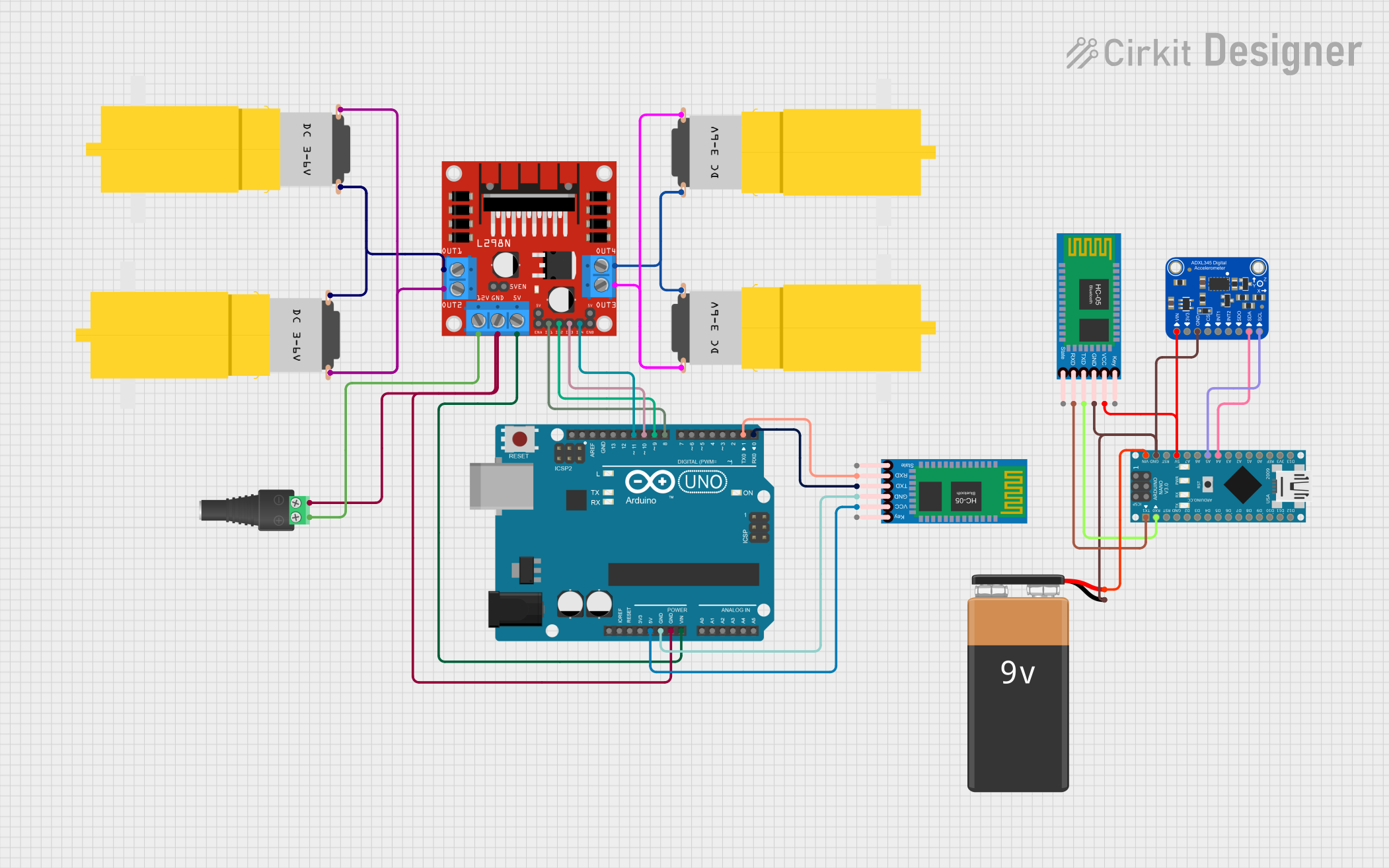
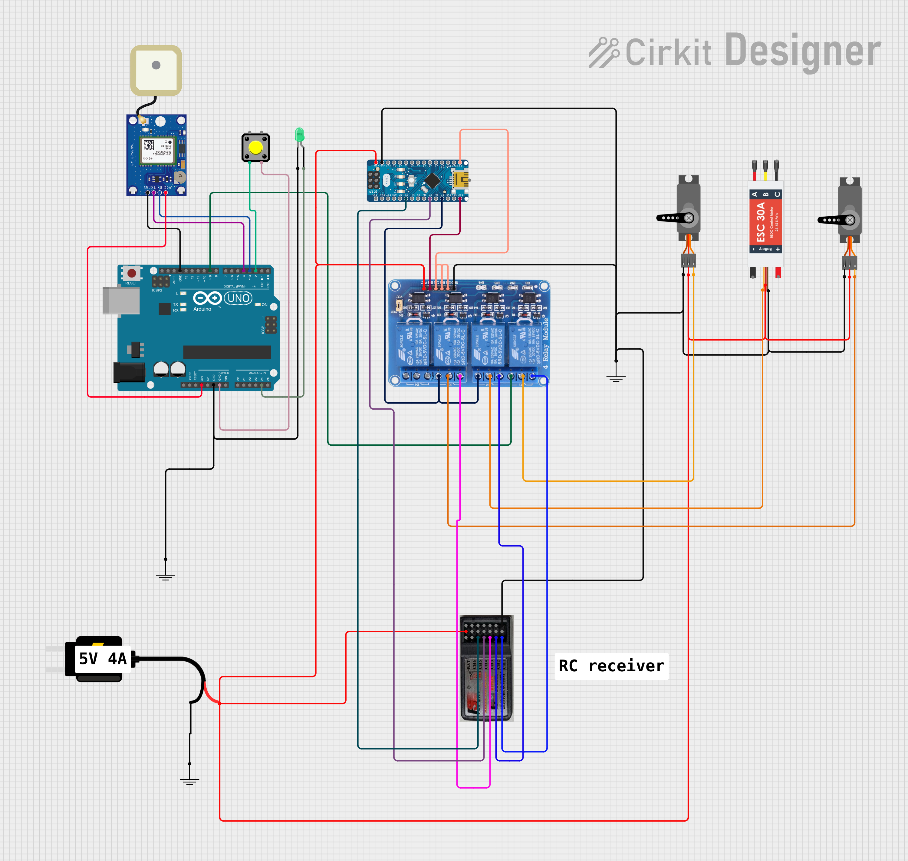

Explore Projects Built with arduino nano
Common Applications
- Prototyping small electronic circuits
- IoT (Internet of Things) devices
- Robotics and automation
- Wearable electronics
- Sensor data acquisition and processing
Technical Specifications
Key Technical Details
| Parameter | Specification |
|---|---|
| Microcontroller | ATmega328P |
| Operating Voltage | 5V |
| Input Voltage (VIN) | 7-12V |
| Digital I/O Pins | 14 (6 PWM outputs) |
| Analog Input Pins | 8 |
| DC Current per I/O Pin | 40 mA |
| Flash Memory | 32 KB (2 KB used by bootloader) |
| SRAM | 2 KB |
| EEPROM | 1 KB |
| Clock Speed | 16 MHz |
| USB Connectivity | Mini-USB |
| Dimensions | 45 mm x 18 mm |
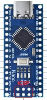
Pin Configuration and Descriptions
The Arduino Nano has a total of 30 pins, including power, digital, and analog pins. Below is the pin configuration:
Power Pins
| Pin Name | Description |
|---|---|
| VIN | Input voltage to the board when using an external power source (7-12V). |
| 5V | Regulated 5V output from the onboard voltage regulator. |
| 3.3V | Regulated 3.3V output (maximum current: 50 mA). |
| GND | Ground pins (multiple GND pins available). |
| RESET | Resets the microcontroller when connected to GND. |
Digital Pins
| Pin Number | Description |
|---|---|
| D0 - D13 | General-purpose digital I/O pins. Pins D3, D5, D6, D9, D10, and D11 |
| support PWM output. |
Analog Pins
| Pin Number | Description |
|---|---|
| A0 - A7 | Analog input pins (10-bit resolution). Can also be used as digital pins. |
Communication Pins
| Pin Name | Description |
|---|---|
| TX (D1) | Transmit pin for serial communication. |
| RX (D0) | Receive pin for serial communication. |
| A4 (SDA) | I2C data line. |
| A5 (SCL) | I2C clock line. |
Usage Instructions
How to Use the Arduino Nano in a Circuit
Powering the Board:
- Use the VIN pin to supply 7-12V from an external power source.
- Alternatively, connect the board to your computer via the Mini-USB port for 5V power.
Connecting Components:
- Use the digital pins (D0-D13) for digital input/output operations.
- Use the analog pins (A0-A7) for reading analog signals (e.g., from sensors).
- For PWM control (e.g., dimming LEDs or controlling motors), use pins D3, D5, D6, D9, D10, or D11.
Programming the Board:
- Install the Arduino IDE from the official Arduino website.
- Connect the Nano to your computer using a Mini-USB cable.
- Select Arduino Nano as the board type and choose the correct COM port in the IDE.
- Write your code and upload it to the board.
Example Code: Blinking an LED
The following example demonstrates how to blink an LED connected to pin D13.
// Define the pin number for the LED
const int ledPin = 13;

void setup() {
  // Set the LED pin as an output
  pinMode(ledPin, OUTPUT);
}

void loop() {
  // Turn the LED on
  digitalWrite(ledPin, HIGH);
  delay(1000); // Wait for 1 second

  // Turn the LED off
  digitalWrite(ledPin, LOW);
  delay(1000); // Wait for 1 second
}
Important Considerations
- Ensure the input voltage does not exceed the specified range (7-12V) to avoid damaging the board.
- Avoid drawing more than 40 mA from any single I/O pin.
- Use appropriate resistors when connecting LEDs or other components to prevent overcurrent.
Troubleshooting and FAQs
Common Issues and Solutions
The board is not detected by the computer:
- Ensure the Mini-USB cable is functional and supports data transfer.
- Check if the correct drivers are installed for the Arduino Nano.
- Verify that the correct COM port is selected in the Arduino IDE.
Code upload fails:
- Double-check that the correct board type and processor are selected in the IDE.
- Press the RESET button on the Nano before uploading the code.
The board is overheating:
- Verify that the input voltage does not exceed 12V.
- Ensure no short circuits exist in your circuit connections.
Analog readings are unstable:
- Use a capacitor (e.g., 0.1 µF) between the analog input pin and GND to filter noise.
- Ensure proper grounding in your circuit.
FAQs
Q: Can the Arduino Nano be powered via USB?
A: Yes, the Nano can be powered directly through the Mini-USB port, which provides 5V to the board.
Q: What is the maximum current the Nano can supply?
A: The 5V pin can supply up to 500 mA when powered via USB, but this depends on the USB port's capacity.
Q: Can I use the Nano for wireless communication?
A: The Nano does not have built-in wireless capabilities, but you can connect external modules like Bluetooth or Wi-Fi (e.g., HC-05 or ESP8266).
Q: Is the Arduino Nano compatible with shields?
A: The Nano is not directly compatible with standard Arduino shields due to its smaller size, but you can use a Nano breakout board or custom wiring.
By following this documentation, you can effectively utilize the Arduino Nano for a wide range of projects and applications.