Cirkit Designer Logo
Cirkit Designer
Your all-in-one circuit design IDE
Home / 
Component Documentation

How to Use 3S BMS: Examples, Pinouts, and Specs

Image of 3S BMS
Cirkit Designer LogoDesign with 3S BMS in Cirkit Designer

Introduction

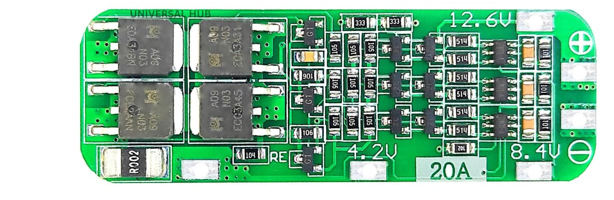
A 3S Battery Management System (BMS) is a crucial component used to monitor and manage the charging and discharging of a 3-cell lithium battery pack. It ensures the safety of the battery pack by preventing overcharging, over-discharging, and short circuits. Additionally, it helps in extending the battery life by balancing the charge across the cells.

Explore Projects Built with 3S BMS

Use Cirkit Designer to design, explore, and prototype these projects online. Some projects support real-time simulation. Click "Open Project" to start designing instantly!
18650 Li-ion Battery Pack with BMS for 5V Power Supply
Image of battary: A project utilizing 3S BMS in a practical application
This circuit consists of a battery management system (BMS) connected to a series of 18650 Li-ion batteries arranged in a 4S configuration to provide a regulated output voltage. The BMS ensures safe charging and discharging of the batteries, while a connector provides a 5V output for external devices.
Cirkit Designer LogoOpen Project in Cirkit Designer
Battery-Powered Servo Control System with 2S 30A BMS and TP5100 Charger
Image of servo power supply: A project utilizing 3S BMS in a practical application
This circuit is a battery management and charging system for a 2S lithium-ion battery pack, which powers multiple MG996R servos. The TP5100 module charges the battery pack from a 12V power supply, while the 2S 30A BMS ensures safe operation and distribution of power to the servos.
Cirkit Designer LogoOpen Project in Cirkit Designer
Battery-Powered 18650 Li-ion Charger with USB Output and Adjustable Voltage Regulator
Image of Breadboard: A project utilizing 3S BMS in a practical application
This circuit is a battery management and power supply system that uses three 3.7V batteries connected to a 3S 10A Li-ion 18650 Charger Protection Board Module for balanced charging and protection. The system includes a TP4056 Battery Charging Protection Module for additional charging safety, a Step Up Boost Power Converter to regulate and boost the voltage, and a USB regulator to provide a stable 5V output, controlled by a push switch.
Cirkit Designer LogoOpen Project in Cirkit Designer
Battery-Powered Adjustable Voltage Regulator with Li-ion 18650 Batteries and BMS
Image of mini ups: A project utilizing 3S BMS in a practical application
This circuit is a power management system that uses four Li-ion 18650 batteries connected to a 2S 30A BMS for battery management and protection. The system includes step-up and step-down voltage regulators to provide adjustable output voltages, controlled by a rocker switch, and multiple DC jacks for power input and output.
Cirkit Designer LogoOpen Project in Cirkit Designer

Explore Projects Built with 3S BMS

Use Cirkit Designer to design, explore, and prototype these projects online. Some projects support real-time simulation. Click "Open Project" to start designing instantly!
Image of battary: A project utilizing 3S BMS in a practical application
18650 Li-ion Battery Pack with BMS for 5V Power Supply
This circuit consists of a battery management system (BMS) connected to a series of 18650 Li-ion batteries arranged in a 4S configuration to provide a regulated output voltage. The BMS ensures safe charging and discharging of the batteries, while a connector provides a 5V output for external devices.
Cirkit Designer LogoOpen Project in Cirkit Designer
Image of servo power supply: A project utilizing 3S BMS in a practical application
Battery-Powered Servo Control System with 2S 30A BMS and TP5100 Charger
This circuit is a battery management and charging system for a 2S lithium-ion battery pack, which powers multiple MG996R servos. The TP5100 module charges the battery pack from a 12V power supply, while the 2S 30A BMS ensures safe operation and distribution of power to the servos.
Cirkit Designer LogoOpen Project in Cirkit Designer
Image of Breadboard: A project utilizing 3S BMS in a practical application
Battery-Powered 18650 Li-ion Charger with USB Output and Adjustable Voltage Regulator
This circuit is a battery management and power supply system that uses three 3.7V batteries connected to a 3S 10A Li-ion 18650 Charger Protection Board Module for balanced charging and protection. The system includes a TP4056 Battery Charging Protection Module for additional charging safety, a Step Up Boost Power Converter to regulate and boost the voltage, and a USB regulator to provide a stable 5V output, controlled by a push switch.
Cirkit Designer LogoOpen Project in Cirkit Designer
Image of mini ups: A project utilizing 3S BMS in a practical application
Battery-Powered Adjustable Voltage Regulator with Li-ion 18650 Batteries and BMS
This circuit is a power management system that uses four Li-ion 18650 batteries connected to a 2S 30A BMS for battery management and protection. The system includes step-up and step-down voltage regulators to provide adjustable output voltages, controlled by a rocker switch, and multiple DC jacks for power input and output.
Cirkit Designer LogoOpen Project in Cirkit Designer

Common Applications and Use Cases

  • Electric Vehicles (EVs): Ensures safe and efficient battery usage.
  • Portable Electronics: Used in devices like laptops and power banks.
  • Renewable Energy Systems: Manages battery packs in solar and wind energy systems.
  • RC Models and Drones: Provides reliable power management for high-performance applications.

Technical Specifications

Key Technical Details

Parameter Value
Battery Configuration 3S (3 cells in series)
Input Voltage Range 9V - 12.6V
Overcharge Voltage 4.25V ± 0.05V per cell
Over-discharge Voltage 2.5V ± 0.1V per cell
Maximum Continuous Current 20A
Balance Current 60mA
Operating Temperature -40°C to 85°C

Pin Configuration and Descriptions

Pin Number Pin Name Description
1 B- Battery negative terminal
2 B1 Connection to the first cell
3 B2 Connection to the second cell
4 B3 Connection to the third cell
5 B+ Battery positive terminal
6 P- Power output negative terminal
7 P+ Power output positive terminal

Usage Instructions

How to Use the Component in a Circuit

  1. Connect the Battery Pack:

    • Connect the negative terminal of the battery pack to the B- pin.
    • Connect the positive terminal of the first cell to the B1 pin.
    • Connect the positive terminal of the second cell to the B2 pin.
    • Connect the positive terminal of the third cell to the B3 pin.
    • Connect the positive terminal of the battery pack to the B+ pin.
  2. Connect the Load/Charger:

    • Connect the negative terminal of the load/charger to the P- pin.
    • Connect the positive terminal of the load/charger to the P+ pin.

Important Considerations and Best Practices

  • Ensure Proper Connections: Double-check all connections to avoid short circuits.
  • Use Appropriate Wire Gauges: Use wires that can handle the maximum current rating.
  • Monitor Temperature: Ensure the BMS operates within the specified temperature range.
  • Balance Charging: Regularly balance charge the battery pack to maintain cell health.

Troubleshooting and FAQs

Common Issues Users Might Face

  1. BMS Not Powering On:

    • Solution: Check all connections and ensure the battery pack is properly connected.
  2. Overcharge/Over-discharge Protection Triggering Frequently:

    • Solution: Verify the cell voltages and ensure they are within the specified range.
  3. Uneven Cell Voltages:

    • Solution: Perform a balance charge to equalize the cell voltages.
  4. Excessive Heat Generation:

    • Solution: Ensure proper ventilation and check for any short circuits.

FAQs

Q1: Can I use the 3S BMS with a different battery configuration?

  • A1: No, the 3S BMS is specifically designed for 3-cell lithium battery packs.

Q2: How do I know if the BMS is balancing the cells?

  • A2: The BMS will automatically balance the cells when the voltage difference exceeds a certain threshold.

Q3: Can I connect the BMS directly to an Arduino UNO?

  • A3: The BMS is not directly interfaced with an Arduino UNO. However, you can monitor the battery pack's voltage and current using appropriate sensors and interface them with the Arduino.

Example Code for Monitoring Battery Voltage with Arduino UNO

// Example code to monitor battery voltage using Arduino UNO
// Connect the voltage divider output to A0 pin of Arduino

const int voltagePin = A0; // Pin connected to voltage divider
float voltage = 0.0;

void setup() {
  Serial.begin(9600); // Initialize serial communication
}

void loop() {
  int sensorValue = analogRead(voltagePin); // Read the analog value
  voltage = sensorValue * (5.0 / 1023.0) * 3; // Convert to voltage
  // Multiply by 3 to account for the voltage divider ratio
  Serial.print("Battery Voltage: ");
  Serial.print(voltage);
  Serial.println(" V");
  delay(1000); // Wait for 1 second before next reading
}

This code reads the voltage from a voltage divider connected to the battery pack and prints it to the serial monitor. Adjust the voltage divider ratio as needed for accurate readings.


This documentation provides a comprehensive guide to understanding, using, and troubleshooting the 3S Battery Management System (BMS). Whether you are a beginner or an experienced user, this guide aims to help you make the most of your BMS.