How to Use Regulator Stepdown DC with LCD Display: Examples, Pinouts, and Specs
Introduction
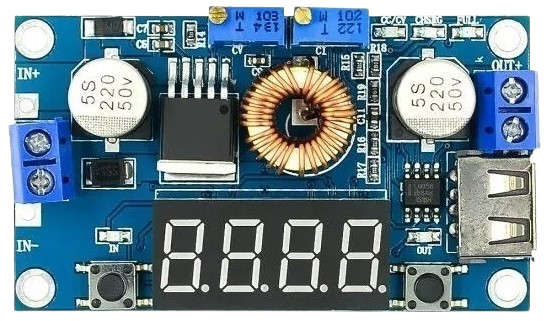
The Regulator Stepdown DC with LCD Display is an electronic module designed to convert a higher DC voltage to a lower DC voltage using a method known as buck conversion. The integrated LCD display provides real-time feedback on the output voltage and current, making it an essential tool for a wide range of applications, including battery charging, power supplies for electronic devices, and as a component in larger electronic systems.
Explore Projects Built with Regulator Stepdown DC with LCD Display
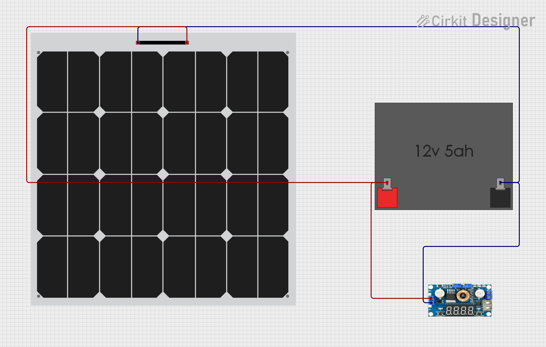
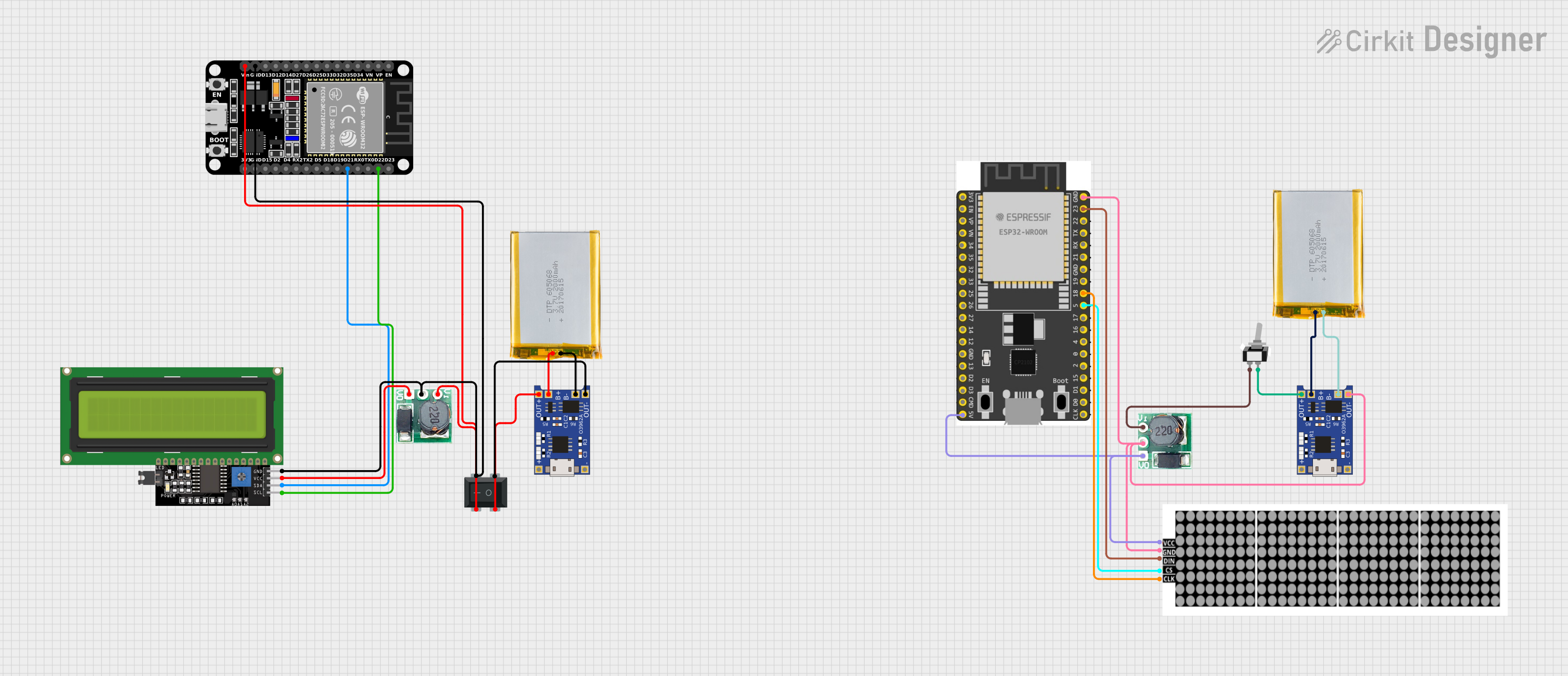


Explore Projects Built with Regulator Stepdown DC with LCD Display
Common Applications and Use Cases
- Powering electronic circuits that require a lower voltage
- Battery charging applications
- DIY electronics projects
- Robotics
- Automotive electronics
Technical Specifications
Key Technical Details
- Input Voltage Range: 6V to 32V DC
- Output Voltage Range: 1.25V to 30V DC (adjustable)
- Output Current: Up to 5A (with proper heat sinking)
- Conversion Efficiency: Up to 95%
- Display: LCD with backlight, showing voltage and current
- Regulation: Switching frequency 150kHz
Pin Configuration and Descriptions
| Pin Number | Name | Description |
|---|---|---|
| 1 | VIN | Input voltage (6V-32V DC) |
| 2 | GND | Ground connection |
| 3 | VOUT | Regulated output voltage (1.25V-30V DC) |
| 4 | GND | Ground connection for output |
Usage Instructions
How to Use the Component in a Circuit
- Connect the input voltage source to the VIN and GND pins, ensuring that the voltage is within the specified range.
- Adjust the onboard potentiometer to set the desired output voltage. The LCD will display the current output voltage.
- Connect the load to the VOUT and GND pins.
- Monitor the output voltage and current on the LCD display during operation.
Important Considerations and Best Practices
- Always ensure the input voltage does not exceed the maximum rating.
- The output voltage must be set before connecting the load.
- For currents above 2A, it is recommended to use heat sinking to prevent overheating.
- Avoid placing the regulator in a high-temperature environment to maintain optimal performance.
- Ensure proper ventilation around the component for adequate air flow.
Troubleshooting and FAQs
Common Issues
- LCD not displaying: Check the input voltage and connections.
- Output voltage is unstable: Ensure that the load does not exceed the maximum current rating and that there is adequate heat sinking.
- Device overheating: Reduce the load current or improve heat dissipation.
Solutions and Tips for Troubleshooting
- If the LCD is not lighting up, verify that the input voltage is within the specified range and that the polarity is correct.
- For unstable output voltage, try adjusting the potentiometer again and check if the load is too high.
- In case of overheating, consider adding a heatsink or a fan to dissipate heat more effectively.
FAQs
Q: Can I use this regulator to charge batteries? A: Yes, but ensure the output voltage is appropriate for the battery being charged.
Q: What is the maximum input voltage for the regulator? A: The maximum input voltage is 32V DC.
Q: How do I adjust the output voltage? A: Use the onboard potentiometer to adjust the output voltage. The LCD display will show the adjusted voltage.
Q: Is it possible to replace the LCD if it fails? A: The LCD is typically soldered to the board and may require desoldering equipment and skills to replace.
Example Arduino UNO Connection Code
// This example demonstrates how to read the output voltage and current from the
// Regulator Stepdown DC with LCD Display using an Arduino UNO.

// Note: This example assumes that the regulator's output voltage and current
// are being converted to a readable format by an ADC or similar means.

void setup() {
  Serial.begin(9600); // Start serial communication at 9600 baud rate.
}

void loop() {
  // Read the voltage and current from the regulator.
  float outputVoltage = analogRead(A0); // Assuming A0 is connected to a voltage divider.
  float outputCurrent = analogRead(A1); // Assuming A1 is connected to a current sensor.

  // Convert the analog readings to meaningful values (depends on the sensor used).
  outputVoltage = map(outputVoltage, 0, 1023, 0, 30); // Example conversion.
  outputCurrent = map(outputCurrent, 0, 1023, 0, 5);   // Example conversion.

  // Print the voltage and current to the Serial Monitor.
  Serial.print("Output Voltage: ");
  Serial.print(outputVoltage);
  Serial.println(" V");

  Serial.print("Output Current: ");
  Serial.print(outputCurrent);
  Serial.println(" A");

  delay(1000); // Wait for 1 second before reading again.
}
Note: The above code is a simple representation and does not account for the actual calibration required to accurately read voltage and current. The map function is used for demonstration purposes and would need to be replaced with a proper conversion based on the specific sensors and ADC resolution used in your project.