How to Use mic: Examples, Pinouts, and Specs
Introduction
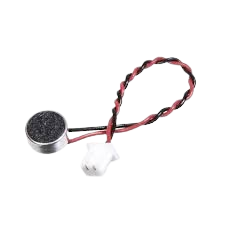
A microphone (mic) is a device that converts sound waves into electrical signals, enabling the capture and transmission of audio. Microphones are widely used in various applications, including audio recording, communication systems, voice recognition, and sound sensing in IoT devices. They are essential components in devices such as smartphones, computers, hearing aids, and public address systems.
Microphones come in different types, such as dynamic, condenser, and electret, each suited for specific use cases. This documentation focuses on the electret microphone, a popular choice for electronics projects due to its small size, low cost, and ease of integration.
Explore Projects Built with mic
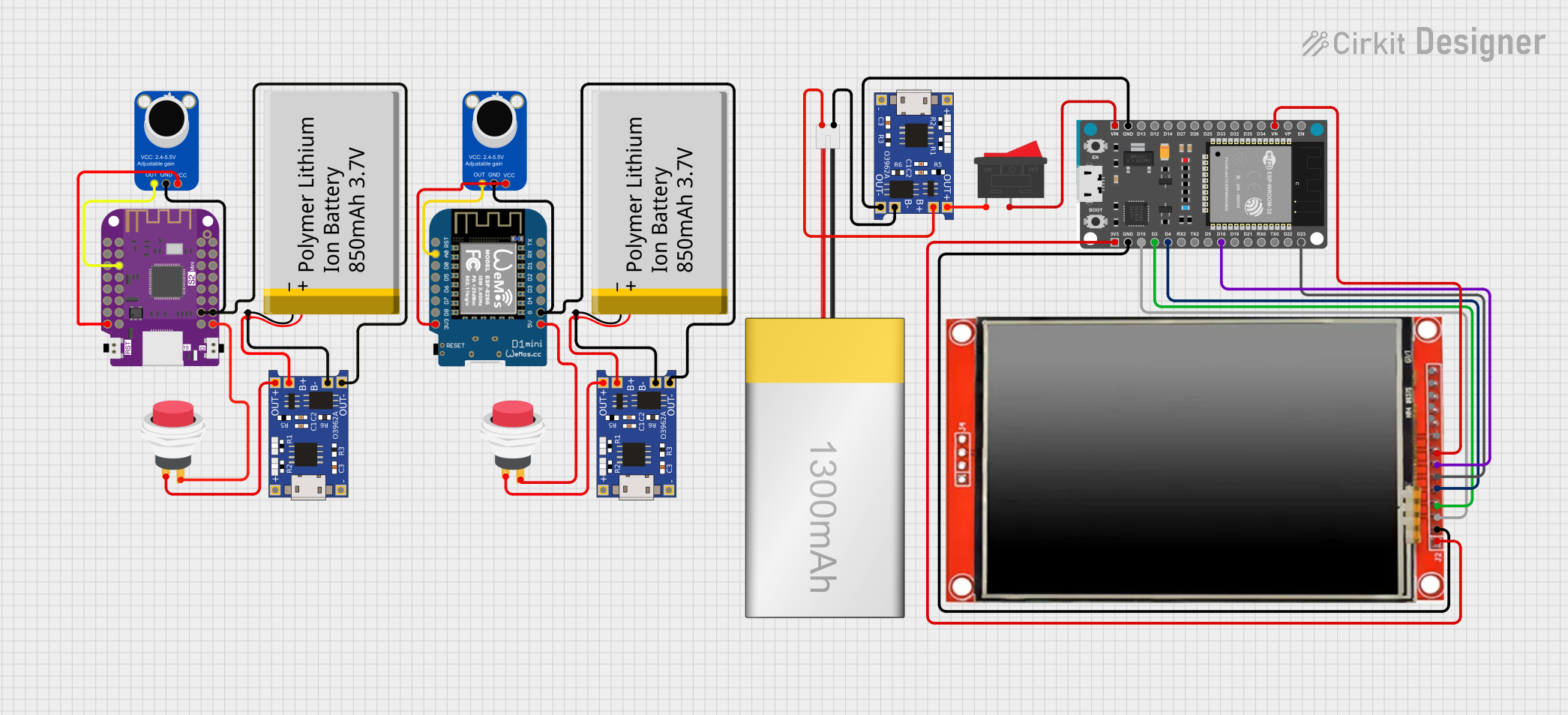
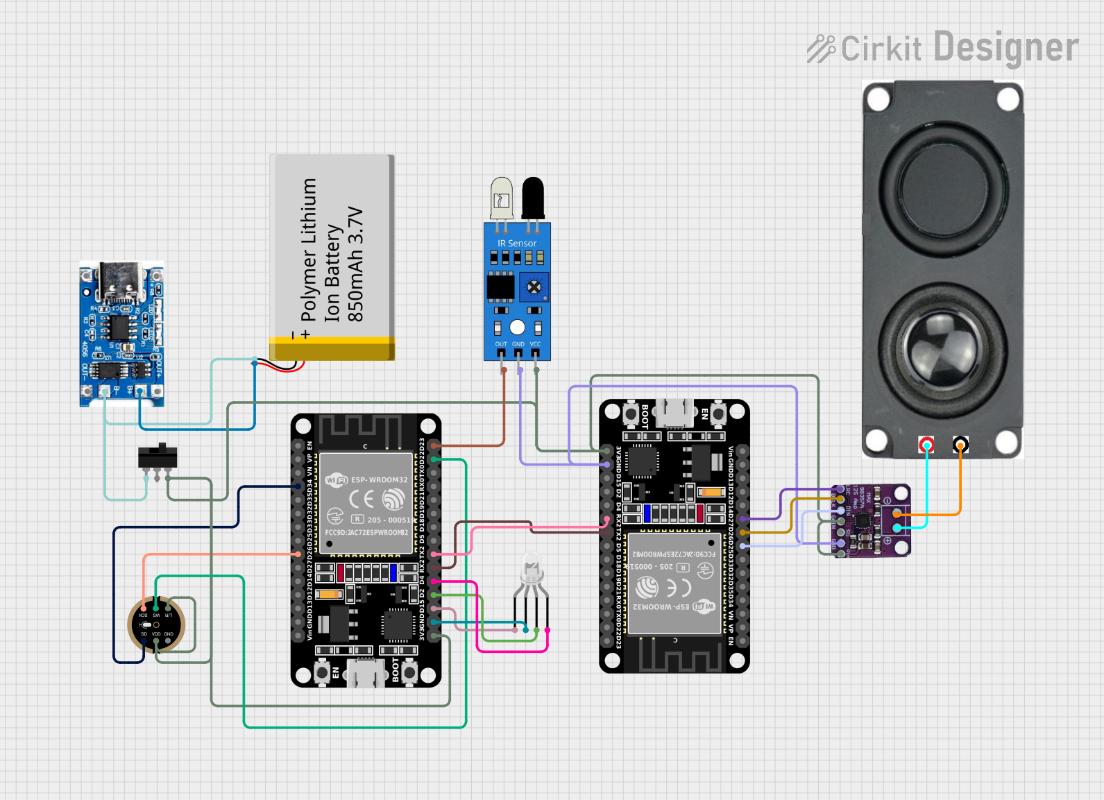
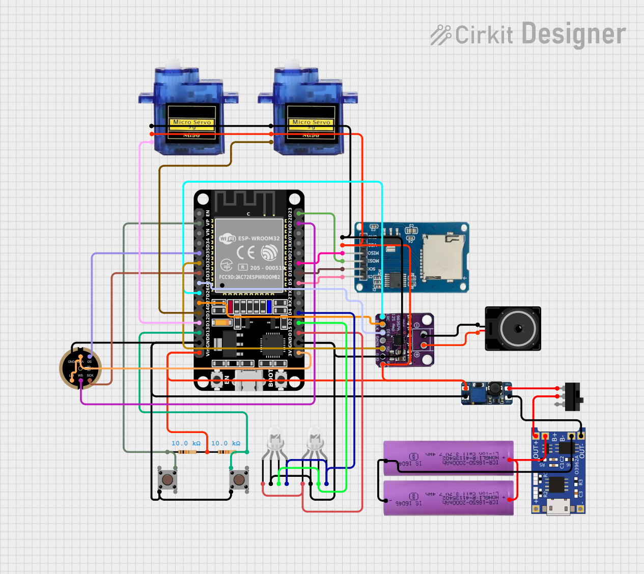
Explore Projects Built with mic
Technical Specifications
Below are the typical technical specifications for an electret microphone:
- Operating Voltage: 1.5V to 10V DC
- Current Consumption: 0.5mA to 0.8mA
- Frequency Response: 20Hz to 20kHz
- Sensitivity: -44dB ± 2dB (at 1kHz, 1Pa)
- Impedance: 2.2kΩ
- Signal-to-Noise Ratio (SNR): ≥ 60dB
- Output Type: Analog
Pin Configuration and Descriptions
Electret microphones typically have two or three pins. Below is the pin configuration for a common two-pin electret microphone:
| Pin | Name | Description |
|---|---|---|
| 1 | V+ (Power) | Connects to the positive voltage supply (typically 3.3V or 5V). |
| 2 | GND | Connects to the ground of the circuit. |
For a three-pin microphone module (e.g., with a built-in amplifier), the configuration is as follows:
| Pin | Name | Description |
|---|---|---|
| 1 | V+ (Power) | Connects to the positive voltage supply (typically 3.3V or 5V). |
| 2 | OUT | Analog audio signal output. |
| 3 | GND | Connects to the ground of the circuit. |
Usage Instructions
How to Use the Microphone in a Circuit
- Power Supply: Connect the V+ pin to a stable DC voltage source (e.g., 3.3V or 5V). Ensure the voltage is within the operating range of the microphone.
- Ground Connection: Connect the GND pin to the ground of your circuit.
- Signal Output: For a two-pin microphone, the output signal is typically superimposed on the power line. Use a coupling capacitor to extract the audio signal. For a three-pin microphone module, connect the OUT pin to the input of an amplifier or microcontroller ADC pin.
- Amplification: The raw output of an electret microphone is weak and often requires amplification. Use an operational amplifier (op-amp) or a pre-built microphone amplifier module for this purpose.
Important Considerations and Best Practices
- Decoupling Capacitor: Use a decoupling capacitor (e.g., 10µF) between the power supply and ground to reduce noise.
- Coupling Capacitor: Place a coupling capacitor (e.g., 1µF) in series with the output signal to block DC offset.
- Avoid Overvoltage: Do not exceed the maximum operating voltage of the microphone to prevent damage.
- Shielding: Use shielded cables or enclosures to minimize interference from external noise sources.
- Placement: Position the microphone away from high-power components or noisy environments to ensure clear audio capture.
Example: Connecting a Microphone to an Arduino UNO
Below is an example of how to connect a microphone module to an Arduino UNO and read the audio signal:
Circuit Connections
- Connect the V+ pin of the microphone module to the 5V pin on the Arduino.
- Connect the GND pin of the microphone module to the GND pin on the Arduino.
- Connect the OUT pin of the microphone module to an analog input pin (e.g., A0) on the Arduino.
Arduino Code
// Microphone signal reading example with Arduino UNO
// This code reads the analog signal from the microphone and prints the values
// to the Serial Monitor for visualization.

const int micPin = A0; // Microphone output connected to analog pin A0

void setup() {
  Serial.begin(9600); // Initialize serial communication at 9600 baud
}

void loop() {
  int micValue = analogRead(micPin); // Read the analog value from the microphone
  Serial.println(micValue);         // Print the value to the Serial Monitor
  delay(10);                        // Small delay to stabilize readings
}
Troubleshooting and FAQs
Common Issues and Solutions
No Output Signal:
- Ensure the microphone is powered correctly and the connections are secure.
- Check if the coupling capacitor is properly connected to extract the audio signal.
Weak or Distorted Signal:
- Verify that the microphone is not placed too far from the sound source.
- Use an amplifier to boost the signal strength if necessary.
- Ensure the power supply is stable and free from noise.
High Noise or Interference:
- Use shielded cables to reduce electromagnetic interference.
- Add a decoupling capacitor to the power supply to filter out noise.
Arduino Reads Constant Values:
- Check if the microphone module's output is connected to the correct analog pin.
- Ensure the microphone is functioning by testing it with an external amplifier or oscilloscope.
FAQs
Q1: Can I use the microphone with a 3.3V power supply?
A1: Yes, most electret microphones and modules can operate with a 3.3V supply. However, check the specific voltage range in the datasheet of your microphone.
Q2: Do I need an amplifier for the microphone?
A2: Yes, the raw output of an electret microphone is weak and typically requires amplification for most applications.
Q3: Can I use the microphone to detect specific frequencies?
A3: Yes, you can use a microcontroller with a Fast Fourier Transform (FFT) library to analyze the frequency components of the audio signal.
Q4: How do I protect the microphone from environmental damage?
A4: Use a protective enclosure or foam windscreen to shield the microphone from dust, moisture, and wind noise.