How to Use Terminal 8 pin: Examples, Pinouts, and Specs
Introduction
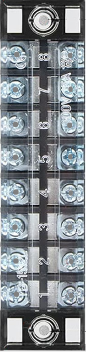
The Terminal 8 Pin is a versatile connector designed to facilitate electrical connections in circuits. It features eight individual pins, allowing for the attachment and detachment of wires with ease. This component is widely used in applications where modularity, flexibility, and reliable connections are required. Its robust design ensures durability and consistent performance in various environments.
Explore Projects Built with Terminal 8 pin


Explore Projects Built with Terminal 8 pin
Common Applications and Use Cases
- Industrial control systems
- Prototyping and testing circuits
- Home automation projects
- Power distribution in low-voltage systems
- Interfacing sensors and actuators in embedded systems
Technical Specifications
The Terminal 8 Pin is designed to meet the needs of a wide range of electrical and electronic applications. Below are its key technical details:
General Specifications
| Parameter | Value |
|---|---|
| Manufacturer | Terminal 8 Pin |
| Manufacturer Part ID | Terminal 8 Pin |
| Number of Pins | 8 |
| Rated Voltage | 300V |
| Rated Current | 10A |
| Insulation Resistance | ≥ 500 MΩ |
| Contact Resistance | ≤ 20 mΩ |
| Operating Temperature | -40°C to +105°C |
| Wire Gauge Support | 22-14 AWG |
| Mounting Type | Screw terminal or PCB mount |
| Material | Flame-retardant plastic (housing), copper alloy (pins) |
Pin Configuration and Descriptions
The Terminal 8 Pin features eight identical pins, each designed for secure wire connections. Below is the pin configuration:
| Pin Number | Description | Notes |
|---|---|---|
| 1 | Electrical connection point | Connect to wire or PCB trace |
| 2 | Electrical connection point | Connect to wire or PCB trace |
| 3 | Electrical connection point | Connect to wire or PCB trace |
| 4 | Electrical connection point | Connect to wire or PCB trace |
| 5 | Electrical connection point | Connect to wire or PCB trace |
| 6 | Electrical connection point | Connect to wire or PCB trace |
| 7 | Electrical connection point | Connect to wire or PCB trace |
| 8 | Electrical connection point | Connect to wire or PCB trace |
Usage Instructions
How to Use the Terminal 8 Pin in a Circuit
- Prepare the Wires: Strip the insulation from the ends of the wires you intend to connect. Ensure the exposed wire length matches the terminal's specifications.
- Insert the Wires: Loosen the screws on the terminal block, insert the stripped wire ends into the corresponding pin slots, and tighten the screws to secure the connection.
- Mount the Terminal: If using a PCB-mounted terminal, solder the pins to the PCB pads. For screw-mounted terminals, secure the terminal block to the desired surface.
- Verify Connections: Double-check all connections to ensure they are secure and free of shorts.
Important Considerations and Best Practices
- Wire Gauge: Use wires within the supported range (22-14 AWG) to ensure proper fit and electrical performance.
- Tightening Screws: Avoid overtightening the screws to prevent damage to the wires or the terminal block.
- Environmental Conditions: Ensure the terminal is used within its rated temperature range (-40°C to +105°C) and voltage/current limits.
- Polarity: If the terminal is used in a polarized circuit, label the pins to avoid incorrect connections.
Example: Connecting to an Arduino UNO
The Terminal 8 Pin can be used to interface external components, such as sensors or actuators, with an Arduino UNO. Below is an example of connecting a sensor to an Arduino using the terminal block:
Circuit Diagram
- Connect the sensor's output wire to Pin 1 of the terminal block.
- Connect the terminal block's Pin 1 to the Arduino's analog input pin (e.g., A0).
- Connect the sensor's power and ground wires to Pins 2 and 3 of the terminal block, respectively.
- Connect the terminal block's Pins 2 and 3 to the Arduino's 5V and GND pins.
Arduino Code Example
// Example code for reading a sensor connected via Terminal 8 Pin
const int sensorPin = A0; // Pin A0 is connected to the sensor output
int sensorValue = 0;      // Variable to store the sensor reading

void setup() {
  Serial.begin(9600); // Initialize serial communication at 9600 baud
  pinMode(sensorPin, INPUT); // Set the sensor pin as an input
}

void loop() {
  sensorValue = analogRead(sensorPin); // Read the sensor value
  Serial.print("Sensor Value: ");      // Print the sensor value to the serial monitor
  Serial.println(sensorValue);
  delay(500); // Wait for 500ms before the next reading
}
Troubleshooting and FAQs
Common Issues and Solutions
| Issue | Possible Cause | Solution |
|---|---|---|
| Loose connections | Screws not tightened properly | Tighten the screws securely. |
| Intermittent signal or power loss | Poor wire contact or damaged wire | Check and replace wires if necessary. |
| Overheating of terminal block | Exceeding current or voltage ratings | Ensure the load is within specifications. |
| Difficulty inserting wires | Wire gauge not supported | Use wires within the 22-14 AWG range. |
FAQs
Q: Can the Terminal 8 Pin be used for high-power applications?
A: The terminal is rated for a maximum current of 10A and voltage of 300V. For higher power applications, consider using a terminal block with higher ratings.
Q: Is the Terminal 8 Pin suitable for outdoor use?
A: The terminal is not specifically designed for outdoor use. If used outdoors, ensure it is housed in a weatherproof enclosure.
Q: Can I use stranded wires with this terminal?
A: Yes, stranded wires can be used. However, it is recommended to tin the wire ends or use ferrules for a more secure connection.
Q: How do I clean the terminal block?
A: Use a soft brush or compressed air to remove dust. Avoid using water or solvents that may damage the insulation material.