
How to Use M93C46: Examples, Pinouts, and Specs
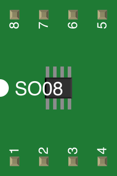
 Design with M93C46 in Cirkit Designer
Introduction
The M93C46 is a 1K-bit electrically erasable programmable read-only memory (EEPROM) manufactured by STMicroelectronics. It operates with a serial interface, making it ideal for applications requiring compact, non-volatile memory storage. The M93C46 supports both 8-bit and 16-bit data organization modes, providing flexibility for various use cases.
Explore Projects Built with M93C46
 Open Project in Cirkit Designer
 Open Project in Cirkit Designer
 Open Project in Cirkit Designer
 Open Project in Cirkit Designer
Explore Projects Built with M93C46
Open Project in Cirkit DesignerOpen Project in Cirkit DesignerOpen Project in Cirkit DesignerOpen Project in Cirkit DesignerCommon Applications
- Configuration data storage in embedded systems
- Calibration data storage for sensors
- Non-volatile memory for microcontroller-based designs
- Secure storage for device identification or authentication keys
- Data logging in industrial and automotive systems
Technical Specifications
Key Technical Details
| Parameter | Value |
|---|---|
| Memory Size | 1 Kbit (128 x 8-bit or 64 x 16-bit) |
| Interface Type | Serial (Microwire-compatible) |
| Operating Voltage Range | 2.5V to 5.5V |
| Maximum Clock Frequency | 2 MHz (at 5V) |
| Write Cycle Time | 5 ms (typical) |
| Data Retention | 40 years |
| Endurance | 1,000,000 write/erase cycles |
| Operating Temperature Range | -40°C to +85°C |
| Package Options | SO8, TSSOP8, and WLCSP |
Pin Configuration and Descriptions
The M93C46 is available in an 8-pin package. Below is the pinout and description:
| Pin No. | Pin Name | Description |
|---|---|---|
| 1 | NC | Not Connected (leave unconnected or grounded) |
| 2 | DO | Data Output (serial data output) |
| 3 | SK | Serial Clock (controls data transfer timing) |
| 4 | GND | Ground |
| 5 | DI | Data Input (serial data input) |
| 6 | CS | Chip Select (enables communication with the chip) |
| 7 | ORG | Organization Select (8-bit or 16-bit mode) |
| 8 | VCC | Power Supply (2.5V to 5.5V) |
Usage Instructions
How to Use the M93C46 in a Circuit
- Power Supply: Connect the VCC pin to a stable power source (2.5V to 5.5V) and the GND pin to ground.
- Chip Select: Use the CS pin to enable or disable communication with the EEPROM. Pull it high to enable communication.
- Clock Signal: Provide a clock signal to the SK pin to synchronize data transfer.
- Data Input/Output: Use the DI pin to send data to the EEPROM and the DO pin to read data from it.
- Organization Mode: Set the ORG pin to configure the memory organization:
- Connect to GND for 16-bit word organization.
- Connect to VCC for 8-bit byte organization.
Important Considerations
- Pull-up Resistors: Use pull-up resistors on the CS and DI lines to ensure proper logic levels.
- Write Protection: Avoid accidental writes by ensuring the CS pin is low when not in use.
- Timing Requirements: Adhere to the timing specifications in the datasheet for reliable operation.
- Decoupling Capacitor: Place a 0.1 µF decoupling capacitor near the VCC pin to filter noise.
Example: Interfacing M93C46 with Arduino UNO
Below is an example of how to interface the M93C46 with an Arduino UNO to write and read data.
Circuit Connections
| M93C46 Pin | Arduino Pin |
|---|---|
| VCC | 5V |
| GND | GND |
| CS | D10 |
| SK | D13 |
| DI | D11 |
| DO | D12 |
| ORG | GND (16-bit mode) |
Arduino Code
#include <SPI.h>

// Define pin connections
const int CS_PIN = 10;

void setup() {
  // Initialize serial communication for debugging
  Serial.begin(9600);

  // Set up SPI and chip select pin
  pinMode(CS_PIN, OUTPUT);
  digitalWrite(CS_PIN, HIGH); // Disable chip by default
  SPI.begin();
}

void loop() {
  // Example: Write data to M93C46
  writeEEPROM(0x00, 0x1234); // Write 16-bit data to address 0x00
  delay(10); // Wait for write cycle to complete

  // Example: Read data from M93C46
  uint16_t data = readEEPROM(0x00);
  Serial.print("Read Data: 0x");
  Serial.println(data, HEX);

  while (1); // Stop execution
}

void writeEEPROM(uint8_t address, uint16_t data) {
  digitalWrite(CS_PIN, LOW); // Enable chip
  SPI.transfer(0x40 | (address & 0x3F)); // Send WRITE opcode and address
  SPI.transfer(data >> 8); // Send high byte of data
  SPI.transfer(data & 0xFF); // Send low byte of data
  digitalWrite(CS_PIN, HIGH); // Disable chip
}

uint16_t readEEPROM(uint8_t address) {
  digitalWrite(CS_PIN, LOW); // Enable chip
  SPI.transfer(0x80 | (address & 0x3F)); // Send READ opcode and address
  uint8_t highByte = SPI.transfer(0x00); // Read high byte
  uint8_t lowByte = SPI.transfer(0x00); // Read low byte
  digitalWrite(CS_PIN, HIGH); // Disable chip
  return (highByte << 8) | lowByte; // Combine high and low bytes
}
Troubleshooting and FAQs
Common Issues
No Data Output on DO Pin:
- Ensure the CS pin is pulled high during communication.
- Verify the clock signal on the SK pin is within the specified frequency range.
Write Operation Fails:
- Check if the power supply voltage is stable and within the operating range.
- Ensure the write cycle time (5 ms) is respected before initiating another operation.
Incorrect Data Read:
- Verify the ORG pin configuration matches the intended data organization (8-bit or 16-bit).
- Check for noise or signal integrity issues on the SPI lines.
FAQs
Q: Can the M93C46 operate at 3.3V?
A: Yes, the M93C46 supports an operating voltage range of 2.5V to 5.5V, making it compatible with 3.3V systems.
Q: How do I protect the EEPROM from accidental writes?
A: Keep the CS pin low when not in use and ensure proper handling of the write enable/disable commands.
Q: What is the maximum clock frequency for the M93C46?
A: The maximum clock frequency is 2 MHz when operating at 5V. For lower voltages, refer to the datasheet for specific limits.