How to Use 74HC86: Examples, Pinouts, and Specs

Introduction
The 74HC86 integrated circuit is a high-speed CMOS device that contains four independent 2-input Exclusive OR (XOR) gates. These gates perform the Boolean function Y = A ⊕ B, where Y is the output and A and B are the inputs. XOR gates are fundamental components in digital electronics, used in applications such as parity generators/checkers, adders, and digital comparators.
Explore Projects Built with 74HC86
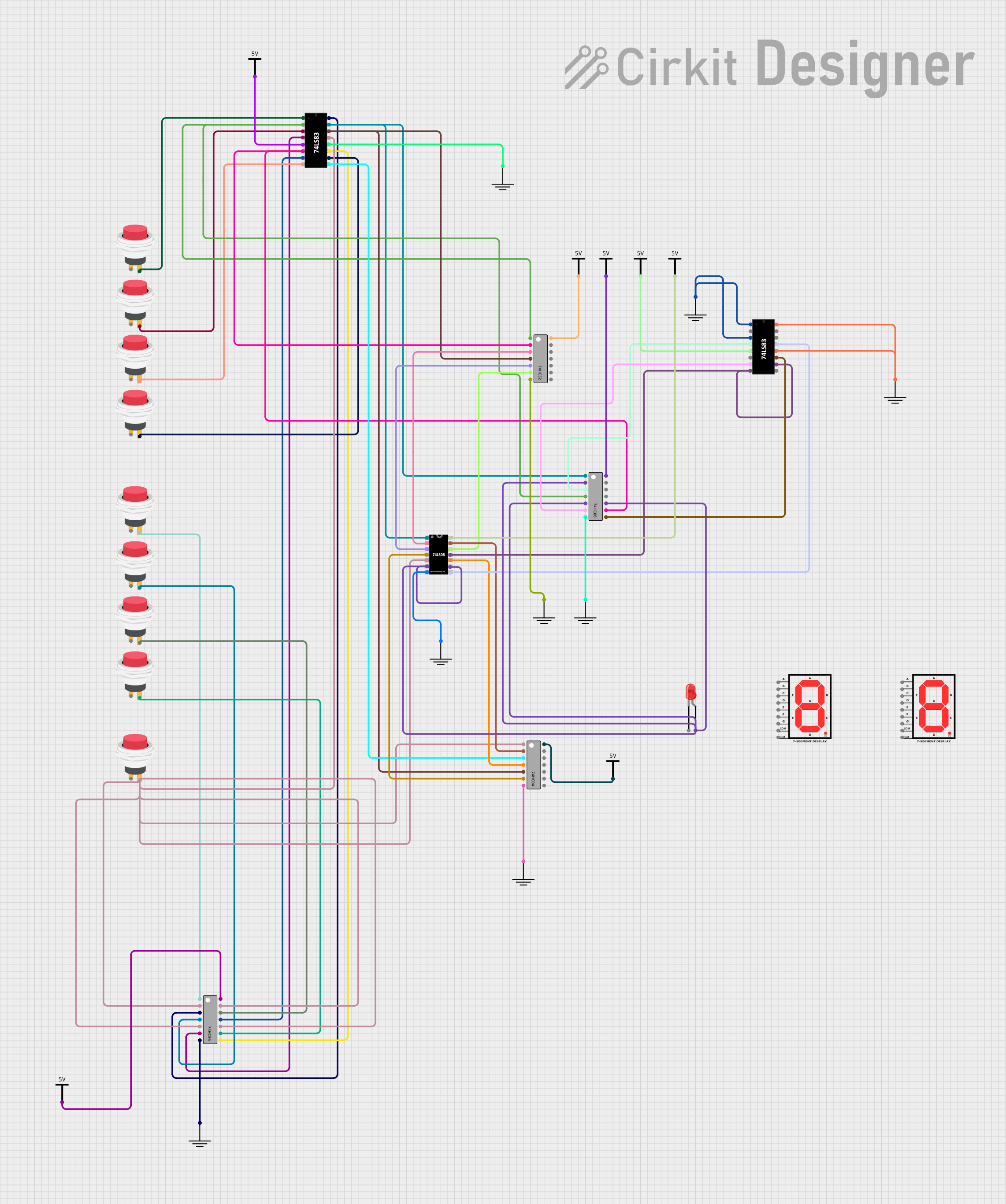


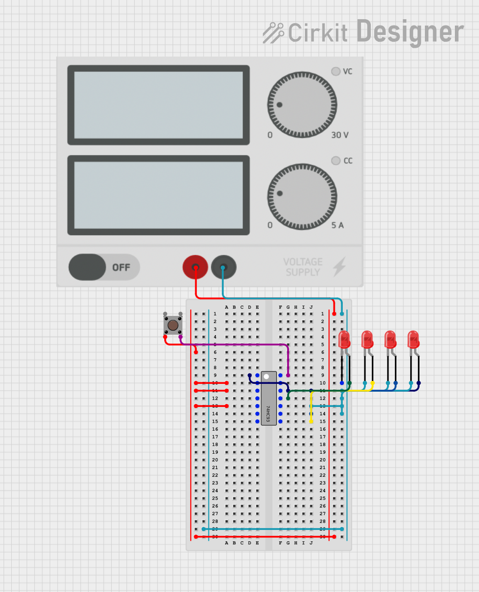
Explore Projects Built with 74HC86
Common Applications
- Digital logic circuits
- Parity generators and checkers
- Binary adders and subtractors
- Encryption systems
- Signal modulation
Technical Specifications
Key Technical Details
- Logic Type: XOR (Exclusive OR)
- Operating Voltage Range: 2V to 6V
- High-Level Output Current: -5.2 mA (max)
- Low-Level Output Current: 5.2 mA (max)
- Propagation Delay Time: 8 ns (typical at Vcc = 5V)
- Operating Temperature Range: -40°C to +125°C
Pin Configuration and Descriptions
| Pin Number | Description |
|---|---|
| 1 | 1A (Input gate 1) |
| 2 | 1B (Input gate 1) |
| 3 | 1Y (Output gate 1) |
| 4 | 2Y (Output gate 2) |
| 5 | 2A (Input gate 2) |
| 6 | 2B (Input gate 2) |
| 7 | GND (Ground) |
| 8 | 3B (Input gate 3) |
| 9 | 3A (Input gate 3) |
| 10 | 3Y (Output gate 3) |
| 11 | 4Y (Output gate 4) |
| 12 | 4A (Input gate 4) |
| 13 | 4B (Input gate 4) |
| 14 | Vcc (Power supply) |
Usage Instructions
How to Use the 74HC86 in a Circuit
Power Supply: Connect pin 14 (Vcc) to a positive power supply within the range of 2V to 6V and pin 7 (GND) to the ground.
Input Signals: Apply the digital signals to the A and B inputs of the gates you intend to use. Ensure that the input voltage levels are compatible with the logic levels of the 74HC86.
Output Connection: Connect the output pins (1Y, 2Y, 3Y, 4Y) to the next stage of your digital circuit or to an output device, ensuring that the current requirements do not exceed the specified limits.
Unused Inputs: For any unused gates, connect the inputs directly to Vcc or GND to avoid floating inputs which can lead to unpredictable behavior.
Important Considerations and Best Practices
- Avoid applying voltages to the inputs when the chip is not powered, as this can damage the device.
- Decoupling capacitors (typically 0.1 µF) should be placed close to the Vcc pin to filter out noise.
- Ensure that the total power dissipation does not exceed the maximum ratings of the package.
Troubleshooting and FAQs
Common Issues
- Floating Inputs: Ensure that all unused inputs are tied to Vcc or GND.
- Output Not Switching: Verify that the input signals are reaching the threshold voltage levels for a logical HIGH or LOW.
- Excessive Power Consumption: Check for short circuits or incorrect connections that may cause higher current draw.
Solutions and Tips
- Use a multimeter to check for continuity and proper voltage levels at the inputs and outputs.
- If the outputs are not as expected, verify the truth table of the XOR gate to ensure correct logic levels are applied.
FAQs
Q: Can I use the 74HC86 at a voltage lower than 2V? A: No, the 74HC86 is designed to operate within a voltage range of 2V to 6V.
Q: What is the maximum frequency the 74HC86 can handle? A: The maximum frequency depends on the supply voltage, but typically the device can handle several megahertz at 5V.
Q: Can I replace a 74LS86 with a 74HC86? A: Yes, but be aware of the differences in power supply levels and output current capabilities between LS (Low-power Schottky) and HC (High-speed CMOS) logic families.
Example Code for Arduino UNO
The following example demonstrates how to use the 74HC86 with an Arduino UNO to perform an XOR operation on two input signals.
// Define the input and output pins
const int inputPinA = 2; // Connect to 1A on 74HC86
const int inputPinB = 3; // Connect to 1B on 74HC86
const int outputPin = 4; // Connect to 1Y on 74HC86

void setup() {
  pinMode(inputPinA, INPUT);
  pinMode(inputPinB, INPUT);
  pinMode(outputPin, OUTPUT);
  Serial.begin(9600);
}

void loop() {
  // Read the input states
  int stateA = digitalRead(inputPinA);
  int stateB = digitalRead(inputPinB);

  // Perform the XOR operation using digital logic
  int xorResult = stateA ^ stateB;

  // Output the result to the 74HC86
  digitalWrite(outputPin, xorResult);

  // Print the result to the Serial Monitor
  Serial.print("Input A: ");
  Serial.print(stateA);
  Serial.print(" Input B: ");
  Serial.print(stateB);
  Serial.print(" XOR Result: ");
  Serial.println(xorResult);

  // Wait for a short period before the next read
  delay(500);
}
Remember to limit the line length of code comments to 80 characters for readability. This example code is a simple demonstration and does not account for debouncing or other input signal conditioning that may be necessary in a real-world application.