How to Use IR Qre1113: Examples, Pinouts, and Specs
Introduction
The IR Qre1113, manufactured by Ziqqucu, is an infrared emitter and detector pair designed for applications requiring object detection, proximity sensing, and remote control systems. This compact and efficient component operates by emitting infrared light and detecting the reflected light from nearby objects, making it ideal for use in robotics, line-following robots, and other automation systems.
Explore Projects Built with IR Qre1113


Explore Projects Built with IR Qre1113
Common Applications
- Line-following robots
- Object detection in robotics
- Proximity sensing
- Remote control systems
- Optical encoders
Technical Specifications
Key Technical Details
| Parameter | Value |
|---|---|
| Manufacturer | Ziqqucu |
| Operating Voltage | 2.7V to 5.5V |
| Operating Current | 25mA (typical) |
| Peak Wavelength | 940nm (infrared light) |
| Detection Range | 0.2mm to 3mm (optimal range) |
| Output Type | Analog |
| Operating Temperature | -25°C to +85°C |
| Package Type | Surface Mount (SMD) |
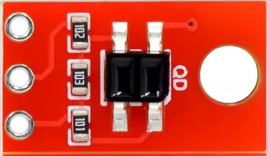
Pin Configuration and Descriptions
The IR Qre1113 has four pins, as described in the table below:
| Pin Number | Name | Description |
|---|---|---|
| 1 | VCC | Power supply pin (2.7V to 5.5V) |
| 2 | GND | Ground pin |
| 3 | OUT | Analog output pin (reflectance-dependent signal) |
| 4 | LED Cathode | Cathode of the infrared LED |
Usage Instructions
How to Use the IR Qre1113 in a Circuit
- Power Supply: Connect the VCC pin to a regulated power source (2.7V to 5.5V) and the GND pin to the ground of the circuit.
- Output Signal: The OUT pin provides an analog voltage signal proportional to the amount of reflected infrared light. This signal can be read by an ADC (Analog-to-Digital Converter) on a microcontroller.
- LED Connection: The LED Cathode pin should be connected to a current-limiting resistor and then to ground. The resistor value can be calculated based on the desired current through the LED.
Important Considerations and Best Practices
- Optimal Distance: The IR Qre1113 works best at a distance of 0.2mm to 3mm from the reflective surface. Ensure the object is within this range for accurate detection.
- Ambient Light: Minimize ambient light interference by shielding the sensor or using it in controlled lighting conditions.
- Current Limiting Resistor: Use a resistor to limit the current through the infrared LED to prevent damage. For example, with a 5V supply and a desired current of 20mA, use a 220Ω resistor.
- Surface Reflectivity: The sensor's output depends on the reflectivity of the surface. Highly reflective surfaces will produce stronger signals.
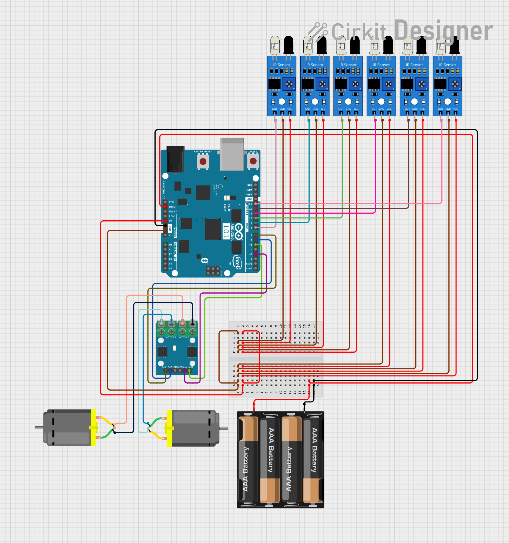
Example: Connecting to an Arduino UNO
Below is an example of how to connect and use the IR Qre1113 with an Arduino UNO:
Circuit Connections
- VCC: Connect to the 5V pin on the Arduino.
- GND: Connect to the GND pin on the Arduino.
- OUT: Connect to an analog input pin (e.g., A0) on the Arduino.
- LED Cathode: Connect to GND through a 220Ω resistor.
Arduino Code
// IR Qre1113 Example Code for Arduino UNO
// This code reads the analog output of the IR Qre1113 and prints the value
// to the Serial Monitor. Ensure the sensor is connected to pin A0.

const int sensorPin = A0; // Analog pin connected to the OUT pin of IR Qre1113

void setup() {
  Serial.begin(9600); // Initialize serial communication at 9600 baud
  pinMode(sensorPin, INPUT); // Set the sensor pin as input
}

void loop() {
  int sensorValue = analogRead(sensorPin); // Read the analog value from the sensor
  Serial.print("Sensor Value: "); // Print label for clarity
  Serial.println(sensorValue); // Print the sensor value to the Serial Monitor
  delay(500); // Wait for 500ms before the next reading
}
Notes:
- Open the Serial Monitor in the Arduino IDE to view the sensor readings.
- Adjust the delay in the
loop()function as needed for your application.
Troubleshooting and FAQs
Common Issues and Solutions
| Issue | Possible Cause | Solution |
|---|---|---|
| No output signal | Incorrect wiring | Double-check all connections and pin labels. |
| Weak or inconsistent signal | Ambient light interference | Shield the sensor from external light sources. |
| Sensor not detecting objects | Object is out of range | Ensure the object is within 0.2mm to 3mm. |
| Overheating of the LED | No current-limiting resistor | Add an appropriate resistor to the LED cathode. |
| Output signal not varying as expected | Surface reflectivity is too low | Use a more reflective surface for testing. |
FAQs
Can the IR Qre1113 detect transparent objects?
No, the sensor is not effective at detecting transparent objects as they do not reflect sufficient infrared light.What is the maximum detection range?
The optimal detection range is 0.2mm to 3mm. Beyond this range, the output signal may become unreliable.Can I use the IR Qre1113 with a 3.3V microcontroller?
Yes, the IR Qre1113 operates within a voltage range of 2.7V to 5.5V, making it compatible with 3.3V systems.How do I improve detection accuracy?
Use the sensor in a controlled environment with minimal ambient light and ensure the object is within the optimal range.
By following this documentation, you can effectively integrate the IR Qre1113 into your projects for reliable infrared sensing and detection.