How to Use Doorsecure AiO: Examples, Pinouts, and Specs
Introduction
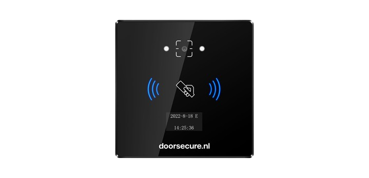
The Doorsecure AiO is an advanced all-in-one access control system designed to provide a comprehensive security solution for various facilities. It integrates multiple access methods including card access, mobile access, biometric recognition, and real-time monitoring into a single, user-friendly unit. This system is ideal for securing sensitive areas in commercial buildings, educational institutions, healthcare facilities, and residential complexes.
Explore Projects Built with Doorsecure AiO
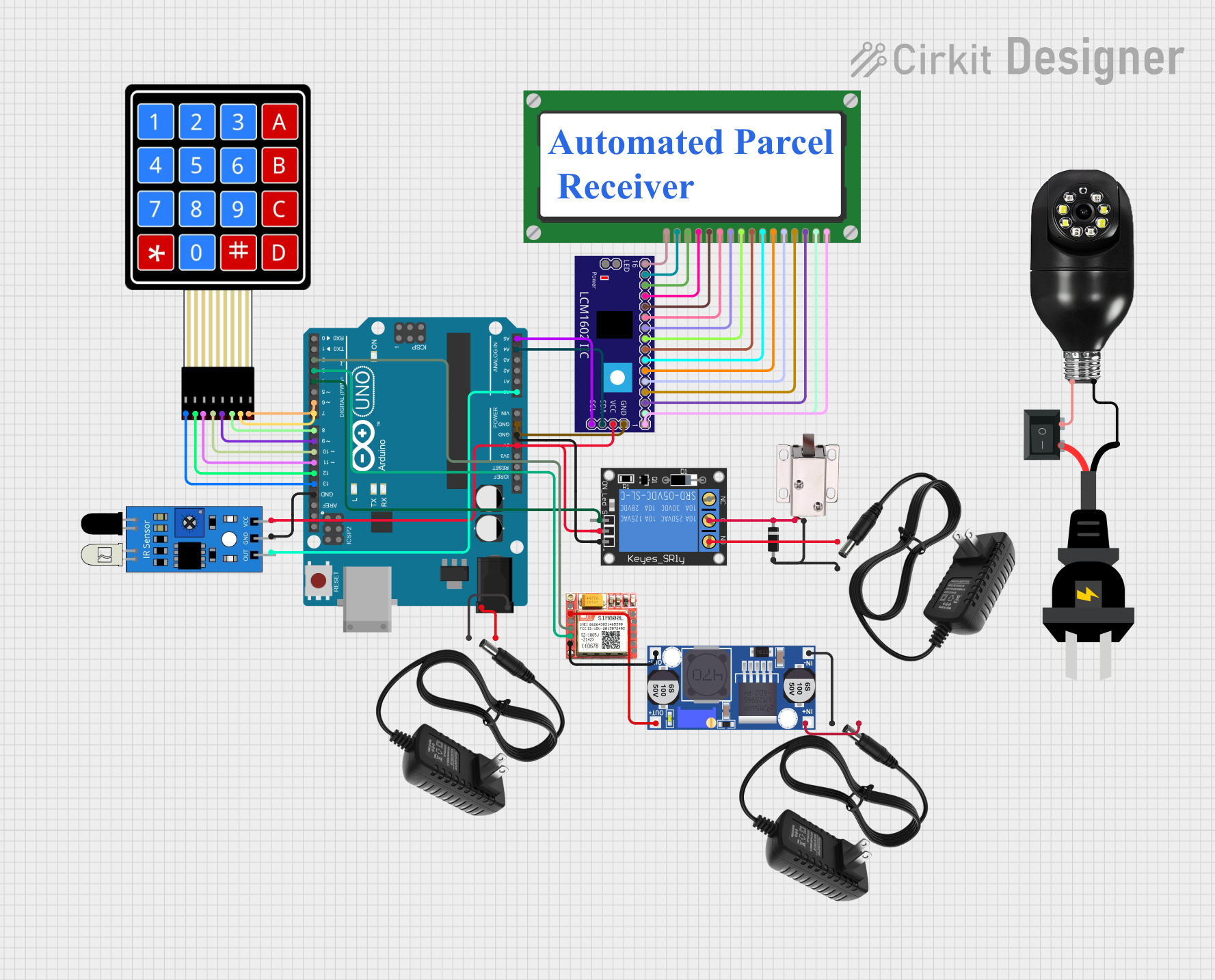
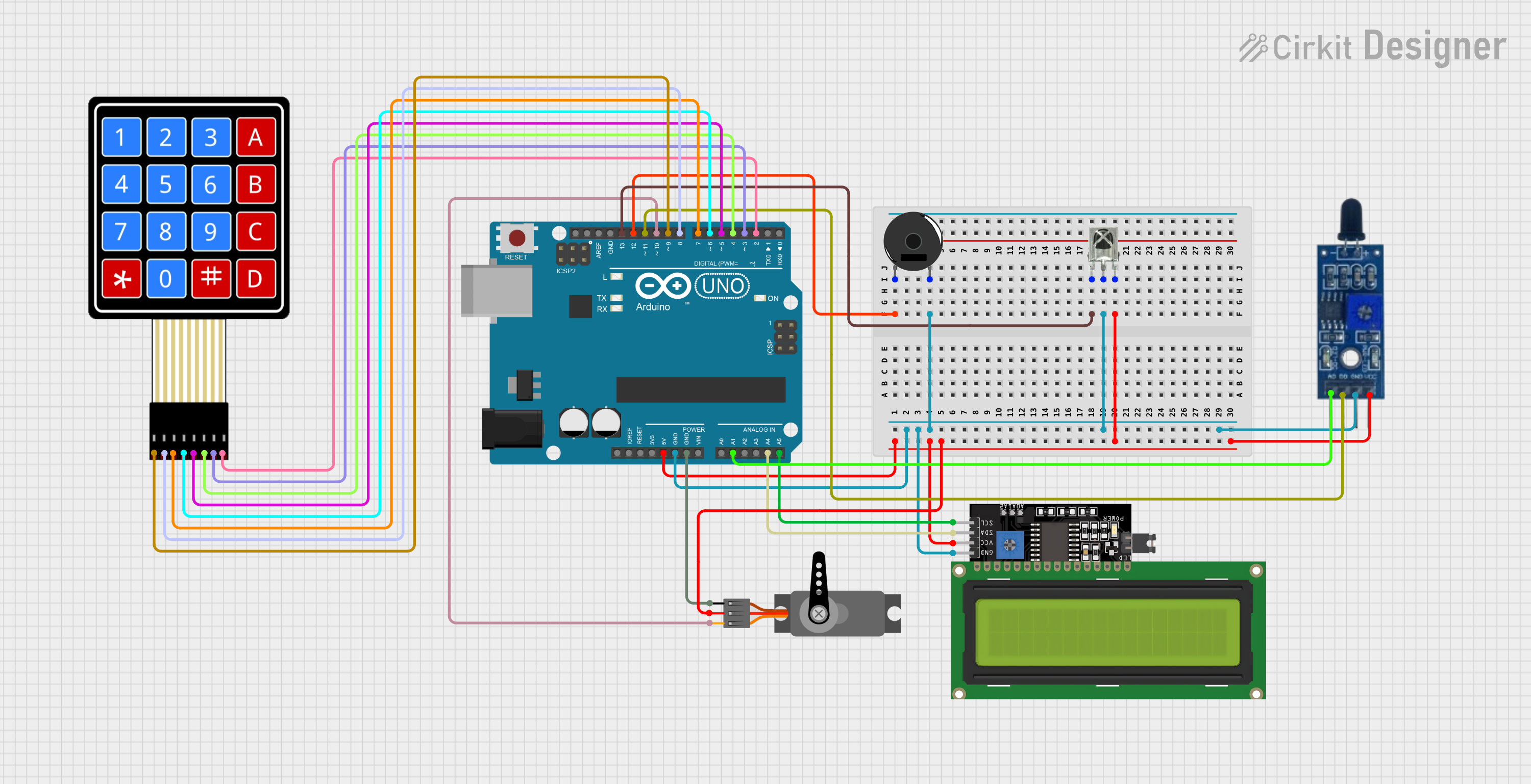
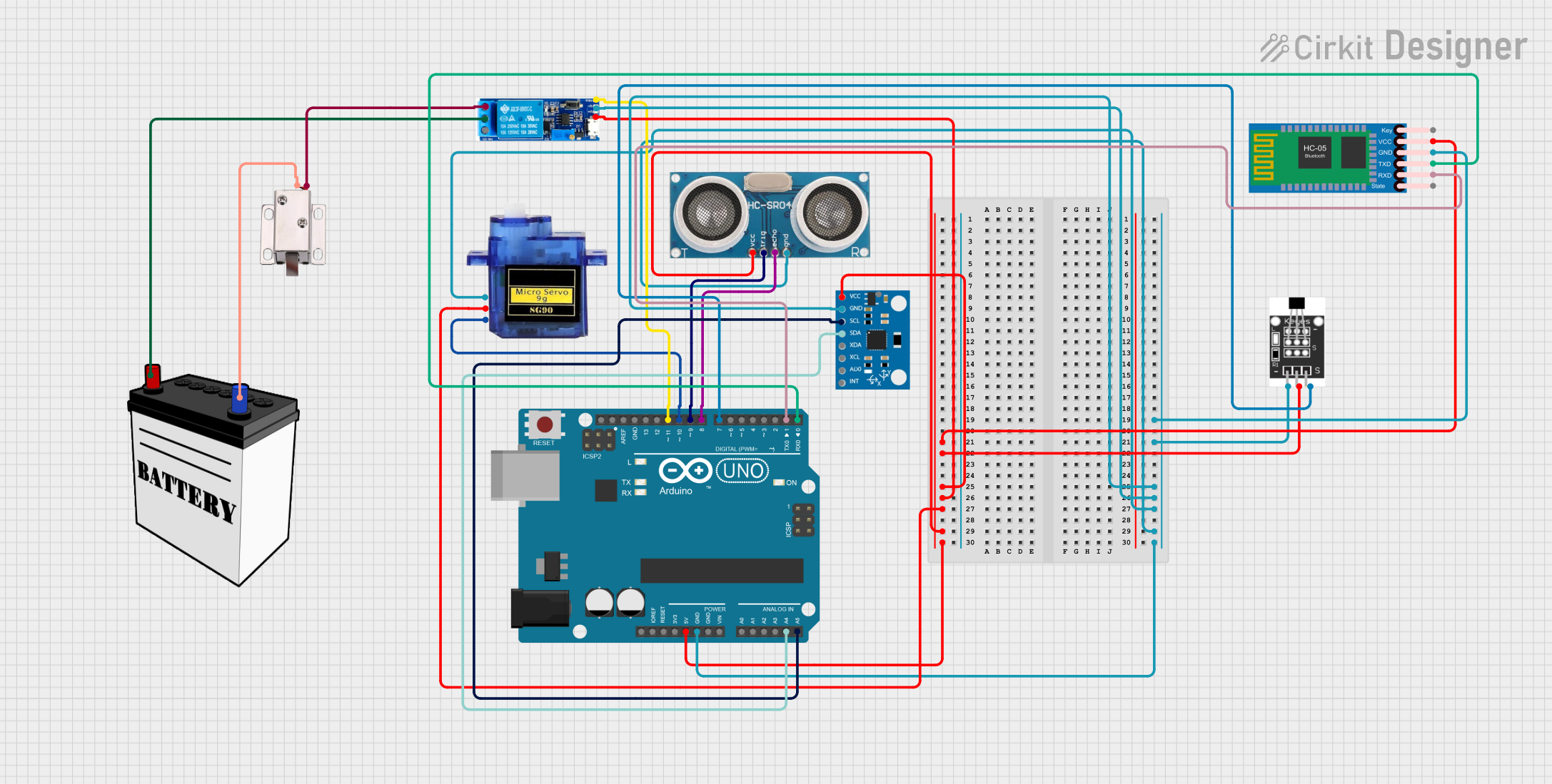
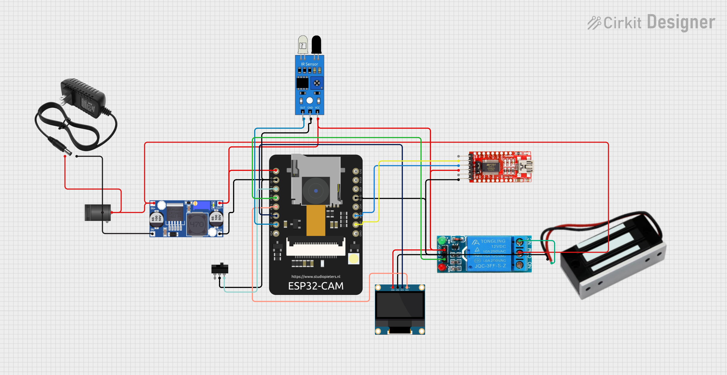
Explore Projects Built with Doorsecure AiO
Common Applications and Use Cases
- Commercial Security: Restrict and monitor access to offices, warehouses, and restricted areas.
- Educational Institutions: Manage entry to classrooms, dormitories, and staff areas.
- Healthcare Facilities: Control access to patient records, pharmacies, and restricted zones.
- Residential Security: Secure entry to apartment buildings, gated communities, and private homes.
Technical Specifications
Key Technical Details
| Specification | Detail |
|---|---|
| Operating Voltage | 12V DC |
| Current Consumption | 500mA (idle), 1A (active) |
| User Capacity | 10,000 users |
| Log Capacity | 100,000 events |
| Communication | TCP/IP, RS485, Wi-Fi, Bluetooth |
| Biometric Sensor | Optical fingerprint sensor |
| Card Reader | RFID and NFC compatible |
| Mobile Access | Via Bluetooth and Wi-Fi |
| Operating Temperature | -10°C to 60°C |
| Dimensions | 145mm x 155mm x 35mm |
Pin Configuration and Descriptions
| Pin Number | Description | Notes |
|---|---|---|
| 1 | 12V DC Input | Power supply input |
| 2 | GND | Ground connection |
| 3 | Relay Output (NO) | Normally open contact for relay |
| 4 | Relay Output (COM) | Common contact for relay |
| 5 | Relay Output (NC) | Normally closed contact for relay |
| 6 | Wiegand D0 | Wiegand interface data 0 |
| 7 | Wiegand D1 | Wiegand interface data 1 |
| 8 | RS485 A | RS485 positive signal |
| 9 | RS485 B | RS485 negative signal |
| 10 | TCP/IP | Ethernet connection |
| 11 | Wi-Fi Antenna | Wireless network connection |
| 12 | Bluetooth Antenna | Bluetooth connection |
Usage Instructions
How to Use the Component in a Circuit
- Power Supply: Connect a 12V DC power supply to pins 1 (12V DC Input) and 2 (GND).
- Relay Connection: Connect the door lock or alarm system to the relay output pins 3 (NO), 4 (COM), and 5 (NC) as required by your application.
- Data Communication: Choose the appropriate communication protocol (Wiegand, RS485, TCP/IP, Wi-Fi, or Bluetooth) and connect it to the corresponding pins or antennas.
- Device Configuration: Set up the device using the manufacturer's software to enroll users, configure access permissions, and customize security settings.
Important Considerations and Best Practices
- Ensure that the power supply is stable and within the specified voltage range to prevent damage.
- Use shielded cables for RS485 communication to minimize interference.
- Place the biometric sensor in an accessible location free from direct sunlight and extreme temperatures.
- Regularly update the system firmware to maintain security and add new features.
- Backup user and log data periodically to prevent loss in case of system failure.
Troubleshooting and FAQs
Common Issues and Solutions
- Power Issues: If the device does not power on, check the power supply and connections to pins 1 and 2.
- Access Denied: Ensure that the user credentials are correctly enrolled and that the access permissions are properly configured.
- Communication Failure: Verify the integrity of the communication lines and ensure that the correct protocol settings are applied.
FAQs
Q: Can the Doorsecure AiO be integrated with other security systems? A: Yes, it can be integrated using standard communication protocols such as Wiegand, RS485, and TCP/IP.
Q: How do I add a new user to the system? A: Use the manufacturer's software to enroll new users by capturing their biometric data, assigning a card, or registering a mobile device.
Q: What should I do if the biometric sensor is not recognizing fingerprints accurately? A: Clean the sensor surface and ensure that users are placing their fingers correctly. If issues persist, recalibrate the sensor using the system settings.
Q: Is the system capable of remote management? A: Yes, with TCP/IP, Wi-Fi, and Bluetooth connectivity, the system can be managed remotely through the appropriate software platform.
Code Example for Arduino UNO Integration
// This example demonstrates how to trigger a relay on the Doorsecure AiO
// using an Arduino UNO when a specific condition is met.

#include <SoftwareSerial.h>

SoftwareSerial rs485(10, 11); // RX, TX for RS485 communication

void setup() {
  rs485.begin(9600); // Initialize RS485 communication at 9600 baud rate
  pinMode(2, OUTPUT); // Relay control pin
}

void loop() {
  // Example condition: Trigger relay when a specific command is received
  if (rs485.available()) {
    if (rs485.read() == 'O') { // Assuming 'O' is the command to open the door
      digitalWrite(2, HIGH); // Activate relay (connect pin 2 to Relay Input)
      delay(5000); // Keep the door open for 5 seconds
      digitalWrite(2, LOW); // Deactivate relay
    }
  }
}
Note: This code is for illustrative purposes only and assumes that the Arduino UNO is interfaced with the Doorsecure AiO system via RS485 communication. The actual implementation may vary based on the specific requirements and the communication protocol used. Always refer to the manufacturer's documentation for precise integration steps.