Cirkit Designer
Your all-in-one circuit design IDE
Home /
Component Documentation
How to Use A9G: Examples, Pinouts, and Specs
Introduction
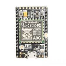
The A9G is a compact GSM/GPRS module with integrated GPS/AGPS capabilities, designed for tracking and communication in IoT applications. This versatile module allows for both data communication over GSM/GPRS networks and precise location tracking using GPS/AGPS. Its small form factor and low power consumption make it ideal for a wide range of applications, including asset tracking, vehicle monitoring, and remote sensing.
Explore Projects Built with A9G
Arduino UNO and A9G GSM/GPRS GPS-Based Air Quality Monitoring System
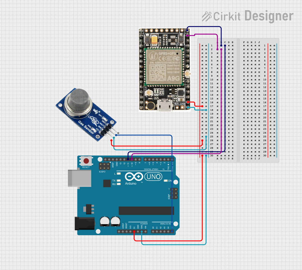
This circuit features an Arduino UNO microcontroller interfaced with an A9G GSM/GPRS+GPS module and an MQ2 gas sensor. The Arduino communicates with the A9G module via digital pins D11 and D10 for data transmission, and it reads analog gas concentration levels from the MQ2 sensor through analog pin A5. Both the A9G module and the MQ2 sensor are powered by the Arduino's 5V output, and all components share a common ground.
Arduino UNO with A9G GSM/GPRS and Dual VL53L1X Distance Sensors

This circuit features an Arduino UNO microcontroller interfaced with an A9G GSM/GPRS+GPS/BDS module and two VL53L1X time-of-flight distance sensors. The A9G module is connected to the Arduino via serial communication for GPS and GSM functionalities, while both VL53L1X sensors are connected through I2C with shared SDA and SCL lines and individual SHUT pins for selective sensor activation. The Arduino is programmed to control these peripherals, although the specific functionality is not detailed in the provided code.
Arduino Nano Health Monitoring System with A9G, MAX30102, and MLX90614 - Battery Powered
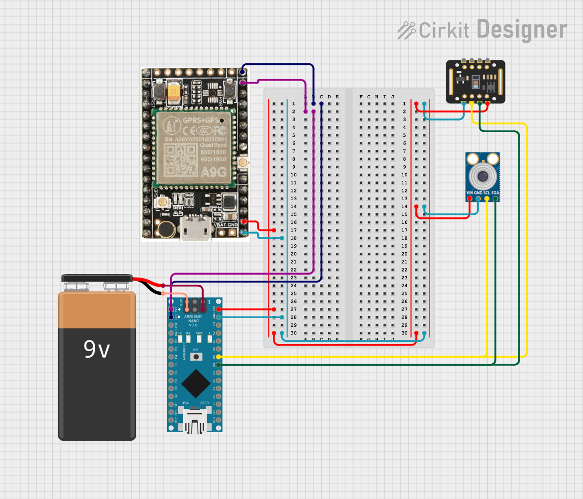
This circuit integrates an Arduino Nano with an A9G GSM/GPRS module, a MAX30102 pulse oximeter, and an MLX90614 infrared thermometer. The Arduino Nano serves as the central controller, interfacing with the sensors via I2C and the A9G module via UART, while being powered by a 9V battery.
Solar-Powered GSM/GPRS+GPS Tracker with Seeeduino XIAO

This circuit features an Ai Thinker A9G development board for GSM/GPRS and GPS/BDS connectivity, interfaced with a Seeeduino XIAO microcontroller for control and data processing. A solar cell, coupled with a TP4056 charging module, charges a 3.3V battery, which powers the system through a 3.3V regulator ensuring stable operation. The circuit likely serves for remote data communication and location tracking, with the capability to be powered by renewable energy and interfaced with additional sensors or input devices via the Seeeduino XIAO.
Explore Projects Built with A9G
Arduino UNO and A9G GSM/GPRS GPS-Based Air Quality Monitoring System
This circuit features an Arduino UNO microcontroller interfaced with an A9G GSM/GPRS+GPS module and an MQ2 gas sensor. The Arduino communicates with the A9G module via digital pins D11 and D10 for data transmission, and it reads analog gas concentration levels from the MQ2 sensor through analog pin A5. Both the A9G module and the MQ2 sensor are powered by the Arduino's 5V output, and all components share a common ground.
Arduino UNO with A9G GSM/GPRS and Dual VL53L1X Distance Sensors
This circuit features an Arduino UNO microcontroller interfaced with an A9G GSM/GPRS+GPS/BDS module and two VL53L1X time-of-flight distance sensors. The A9G module is connected to the Arduino via serial communication for GPS and GSM functionalities, while both VL53L1X sensors are connected through I2C with shared SDA and SCL lines and individual SHUT pins for selective sensor activation. The Arduino is programmed to control these peripherals, although the specific functionality is not detailed in the provided code.
Arduino Nano Health Monitoring System with A9G, MAX30102, and MLX90614 - Battery Powered
This circuit integrates an Arduino Nano with an A9G GSM/GPRS module, a MAX30102 pulse oximeter, and an MLX90614 infrared thermometer. The Arduino Nano serves as the central controller, interfacing with the sensors via I2C and the A9G module via UART, while being powered by a 9V battery.
Solar-Powered GSM/GPRS+GPS Tracker with Seeeduino XIAO
This circuit features an Ai Thinker A9G development board for GSM/GPRS and GPS/BDS connectivity, interfaced with a Seeeduino XIAO microcontroller for control and data processing. A solar cell, coupled with a TP4056 charging module, charges a 3.3V battery, which powers the system through a 3.3V regulator ensuring stable operation. The circuit likely serves for remote data communication and location tracking, with the capability to be powered by renewable energy and interfaced with additional sensors or input devices via the Seeeduino XIAO.
Technical Specifications
Key Technical Details
| Parameter | Value |
|---|---|
| Supply Voltage | 3.3V - 4.2V |
| Operating Current | 20mA (idle), 200mA (active) |
| Peak Current | 2A |
| GSM Frequency | 850/900/1800/1900 MHz |
| GPRS Class | Class 12 |
| GPS Sensitivity | -165 dBm |
| GPS Accuracy | < 2.5m CEP |
| Operating Temperature | -40°C to +85°C |
| Dimensions | 22mm x 20mm x 2.3mm |
Pin Configuration and Descriptions
| Pin Number | Pin Name | Description |
|---|---|---|
| 1 | VCC | Power supply (3.3V - 4.2V) |
| 2 | GND | Ground |
| 3 | TXD | UART Transmit Data |
| 4 | RXD | UART Receive Data |
| 5 | GPS_TXD | GPS UART Transmit Data |
| 6 | GPS_RXD | GPS UART Receive Data |
| 7 | NETLIGHT | Network status indicator |
| 8 | PWRKEY | Power on/off control |
| 9 | RST | Reset |
| 10 | ANT_GSM | GSM antenna |
| 11 | ANT_GPS | GPS antenna |
Usage Instructions
How to Use the A9G in a Circuit
- Power Supply: Connect the VCC pin to a stable power supply within the range of 3.3V to 4.2V. Connect the GND pin to the ground of your circuit.
- UART Communication: Connect the TXD and RXD pins to the corresponding UART pins of your microcontroller (e.g., Arduino UNO). This will enable GSM/GPRS communication.
- GPS Communication: Similarly, connect the GPS_TXD and GPS_RXD pins to another set of UART pins on your microcontroller for GPS data.
- Antenna Connections: Attach the GSM antenna to the ANT_GSM pin and the GPS antenna to the ANT_GPS pin for proper signal reception.
- Power Control: Use the PWRKEY pin to control the power state of the module. Pulling this pin low for 1 second will turn the module on or off.
- Network Status: The NETLIGHT pin can be connected to an LED to indicate network status (blinking indicates network activity).
Important Considerations and Best Practices
- Ensure that the power supply can handle the peak current requirement of 2A to avoid power issues.
- Use appropriate antennas for GSM and GPS to ensure good signal reception.
- Place the module in a location with minimal obstructions for optimal GPS performance.
- Implement proper error handling in your code to manage communication failures.
Example Code for Arduino UNO
#include <SoftwareSerial.h>

// Define the pins for the A9G module
#define A9G_TX 10
#define A9G_RX 11
#define GPS_TX 8
#define GPS_RX 9
#define PWRKEY 7

SoftwareSerial a9gSerial(A9G_RX, A9G_TX);
SoftwareSerial gpsSerial(GPS_RX, GPS_TX);

void setup() {
  // Initialize serial communication with the A9G module
  Serial.begin(9600);
  a9gSerial.begin(9600);
  gpsSerial.begin(9600);

  // Power on the A9G module
  pinMode(PWRKEY, OUTPUT);
  digitalWrite(PWRKEY, LOW);
  delay(1000);
  digitalWrite(PWRKEY, HIGH);

  Serial.println("A9G module initialized.");
}

void loop() {
  // Check for data from the A9G module
  if (a9gSerial.available()) {
    while (a9gSerial.available()) {
      char c = a9gSerial.read();
      Serial.write(c);
    }
  }

  // Check for GPS data
  if (gpsSerial.available()) {
    while (gpsSerial.available()) {
      char c = gpsSerial.read();
      Serial.write(c);
    }
  }

  delay(1000);
}
Troubleshooting and FAQs
Common Issues
No Power/Module Not Responding:
- Ensure the power supply is within the specified range (3.3V - 4.2V).
- Check the PWRKEY pin connection and ensure it is pulled low for at least 1 second to power on the module.
No GSM Network Connection:
- Verify the GSM antenna is properly connected.
- Check the SIM card for proper insertion and activation.
- Ensure the module is in an area with good GSM signal coverage.
No GPS Fix:
- Ensure the GPS antenna is properly connected.
- Place the module in an open area with a clear view of the sky.
- Allow sufficient time for the module to acquire a GPS fix.
Solutions and Tips for Troubleshooting
- Power Issues: Use a power supply capable of delivering at least 2A peak current. Check all power connections and ensure they are secure.
- Communication Issues: Verify the UART connections and ensure the correct baud rate is set in your code. Use a logic analyzer or oscilloscope to debug UART signals if necessary.
- Antenna Issues: Use high-quality antennas and ensure they are properly connected. Avoid placing the module in areas with significant RF interference.
By following this documentation, users should be able to effectively integrate and utilize the A9G module in their IoT projects, ensuring reliable communication and accurate location tracking.