How to Use SpeedyBee 55A 3-6S 4in1 8-bit ESC: Examples, Pinouts, and Specs
Introduction
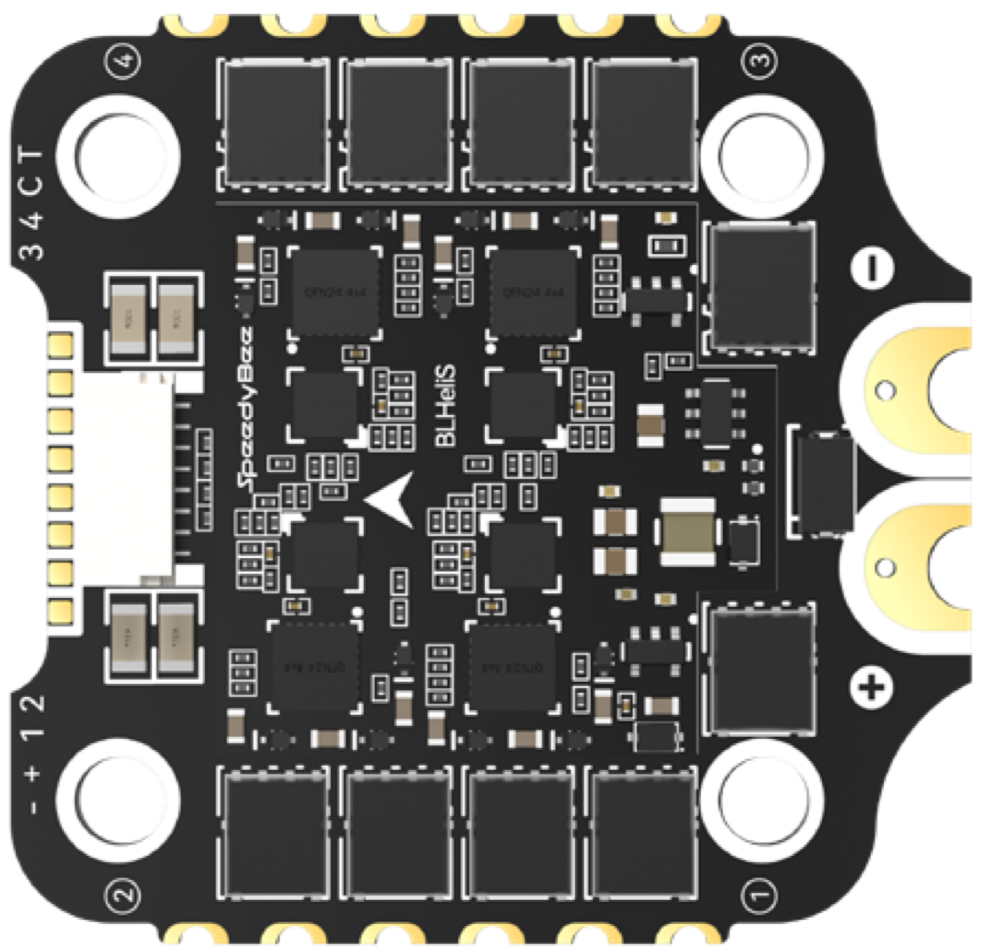
The SpeedyBee 55A 3-6S 4in1 8-bit ESC (Manufacturer Part ID: CAAH-S55) is a high-performance electronic speed controller (ESC) designed specifically for multirotor drones. This compact and efficient ESC integrates four individual ESCs into a single unit, reducing wiring complexity and saving space. It supports a continuous current of up to 55A per channel and is compatible with 3-6S LiPo batteries. With its 8-bit processing, the ESC ensures precise motor control, making it ideal for high-performance drone applications.
Explore Projects Built with SpeedyBee 55A 3-6S 4in1 8-bit ESC


Explore Projects Built with SpeedyBee 55A 3-6S 4in1 8-bit ESC
Common Applications and Use Cases
- Multirotor drones (e.g., quadcopters, hexacopters)
- FPV (First-Person View) racing drones
- Aerial photography and videography platforms
- Hobbyist and professional drone builds
- Compact UAVs requiring high current and efficient motor control
Technical Specifications
Key Technical Details
| Parameter | Value |
|---|---|
| Manufacturer | SpeedyBee |
| Part ID | CAAH-S55 |
| Continuous Current | 55A per channel |
| Peak Current | 60A (for up to 10 seconds) |
| Input Voltage Range | 3S-6S LiPo (11.1V - 25.2V) |
| Processor | 8-bit |
| Firmware | BLHeli_S |
| ESC Type | 4-in-1 |
| Dimensions | 45mm x 37mm x 6mm |
| Weight | 15g |
| Mounting Hole Spacing | 30.5mm x 30.5mm (M3 screws) |
| Signal Input | PWM, Oneshot125, Multishot, DShot |
| Motor Output | 4x motor outputs |
| BEC Output | None |
| Operating Temperature | -20°C to 85°C |
Pin Configuration and Descriptions
The SpeedyBee 55A 3-6S 4in1 ESC features a connector for signal input and power distribution. Below is the pinout description:
Signal Input Connector
| Pin Number | Label | Description |
|---|---|---|
| 1 | M1 | Signal input for Motor 1 |
| 2 | M2 | Signal input for Motor 2 |
| 3 | M3 | Signal input for Motor 3 |
| 4 | M4 | Signal input for Motor 4 |
| 5 | GND | Ground connection for signal input |
| 6 | 5V | 5V output for powering the flight controller |
Power Input Pads
| Pad Label | Description |
|---|---|
| VBAT+ | Positive terminal for LiPo battery input |
| VBAT- | Negative terminal for LiPo battery input |
Motor Output Pads
| Pad Label | Description |
|---|---|
| M1+ / M1- | Positive and negative terminals for Motor 1 |
| M2+ / M2- | Positive and negative terminals for Motor 2 |
| M3+ / M3- | Positive and negative terminals for Motor 3 |
| M4+ / M4- | Positive and negative terminals for Motor 4 |
Usage Instructions
How to Use the Component in a Circuit
- Mounting the ESC: Secure the ESC to your drone frame using M3 screws and ensure proper alignment with the flight controller.
- Connecting the Motors: Solder the motor wires to the corresponding motor output pads (M1, M2, M3, M4). Ensure correct polarity.
- Power Input: Solder the LiPo battery leads to the VBAT+ and VBAT- pads. Use appropriate gauge wires to handle high current.
- Signal Input: Connect the signal input pins (M1, M2, M3, M4, GND, 5V) to the flight controller. Ensure the signal wires match the motor order in the flight controller configuration.
- Firmware Configuration: Use BLHeliSuite or BLHeli Configurator to configure the ESC firmware. Set the desired protocol (e.g., DShot600) and calibrate the ESCs if necessary.
- Testing: Before flying, test the motor directions and ensure all connections are secure.
Important Considerations and Best Practices
- Cooling: Ensure adequate airflow over the ESC to prevent overheating during operation.
- Battery Compatibility: Use only 3S-6S LiPo batteries within the specified voltage range.
- Signal Protocol: Verify that your flight controller supports the selected signal protocol (e.g., DShot, PWM).
- Soldering: Use high-quality solder and ensure all connections are clean and secure to avoid electrical issues.
- Motor Calibration: Calibrate the ESCs using BLHeli software to ensure synchronized motor operation.
Example Code for Arduino UNO (PWM Signal Control)
The SpeedyBee 55A ESC can be controlled using PWM signals. Below is an example code to control a single motor using an Arduino UNO:
#include <Servo.h> // Include the Servo library for PWM signal generation

Servo motor1; // Create a Servo object for Motor 1

void setup() {
  motor1.attach(9); // Attach Motor 1 signal to pin 9
  motor1.writeMicroseconds(1000); // Send minimum throttle signal (1000us)
  delay(5000); // Wait for ESC to initialize
}

void loop() {
  motor1.writeMicroseconds(1500); // Set throttle to mid-range (1500us)
  delay(5000); // Run motor at mid-throttle for 5 seconds

  motor1.writeMicroseconds(1000); // Set throttle to minimum (1000us)
  delay(5000); // Stop motor for 5 seconds
}
Note: Ensure the ESC is properly powered and connected to the Arduino UNO before running the code.
Troubleshooting and FAQs
Common Issues and Solutions
Motors Not Spinning
- Cause: Incorrect signal connection or protocol mismatch.
- Solution: Verify signal connections and ensure the flight controller is configured with the correct protocol (e.g., DShot600).
Overheating
- Cause: Insufficient cooling or excessive current draw.
- Solution: Improve airflow over the ESC and ensure motors and propellers are within the recommended specifications.
ESC Not Initializing
- Cause: Incorrect power connection or firmware issue.
- Solution: Check the battery voltage and ensure proper soldering of power leads. Reflash the firmware if necessary.
Motor Spinning in the Wrong Direction
- Cause: Incorrect motor wiring.
- Solution: Swap any two motor wires to reverse the direction or configure the motor direction in BLHeli software.
FAQs
Can I use this ESC with a 2S LiPo battery?
- No, the ESC is designed for 3S-6S LiPo batteries only. Using a 2S battery may result in improper operation.
Does the ESC have a built-in BEC?
- No, the ESC does not include a BEC. Use an external BEC or power the flight controller separately.
What signal protocols are supported?
- The ESC supports PWM, Oneshot125, Multishot, and DShot protocols.
Can I use this ESC for fixed-wing aircraft?
- While it is possible, this ESC is optimized for multirotor applications and may not be ideal for fixed-wing setups.
This concludes the documentation for the SpeedyBee 55A 3-6S 4in1 8-bit ESC. For further assistance, refer to the manufacturer's support resources or contact SpeedyBee directly.