How to Use S6609 Stepper motor driver: Examples, Pinouts, and Specs
Introduction
The S6609 Stepper Motor Driver, manufactured by OpenSource, is a versatile and reliable driver designed to control stepper motors with precision and efficiency. It supports microstepping, adjustable current control, and built-in protection features, making it ideal for applications requiring smooth and accurate motor positioning. The S6609 is commonly used in 3D printers, CNC machines, robotics, and other motion control systems.
Explore Projects Built with S6609 Stepper motor driver


Explore Projects Built with S6609 Stepper motor driver
Common Applications
- 3D Printers: For precise layer positioning and smooth motion.
- CNC Machines: To control stepper motors for cutting, engraving, or milling.
- Robotics: For accurate movement and positioning of robotic arms or wheels.
- Automation Systems: In conveyor belts, pick-and-place machines, and other automated equipment.
Technical Specifications
Key Technical Details
| Parameter | Value |
|---|---|
| Operating Voltage | 8V to 35V DC |
| Maximum Output Current | 2.5A per phase (adjustable) |
| Microstepping Resolution | Full, 1/2, 1/4, 1/8, 1/16 steps |
| Logic Voltage | 3.3V or 5V compatible |
| Control Interface | Step and Direction inputs |
| Protection Features | Overcurrent, Overtemperature, and Undervoltage Lockout |
| Operating Temperature | -20°C to 85°C |
Pin Configuration and Descriptions
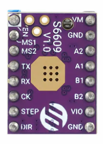
The S6609 has a standard 16-pin configuration. Below is the pinout and description:
| Pin Number | Pin Name | Description |
|---|---|---|
| 1 | VMOT | Motor power supply (8V to 35V DC). Connect to the motor power source. |
| 2 | GND | Ground connection for motor power supply. |
| 3 | A+ | Positive terminal of motor coil A. |
| 4 | A- | Negative terminal of motor coil A. |
| 5 | B+ | Positive terminal of motor coil B. |
| 6 | B- | Negative terminal of motor coil B. |
| 7 | VDD | Logic power supply (3.3V or 5V). |
| 8 | GND | Ground connection for logic power supply. |
| 9 | STEP | Step pulse input. Each pulse moves the motor one step (or microstep). |
| 10 | DIR | Direction control input. High or low determines the motor's rotation direction. |
| 11 | ENABLE | Enable input. Active low to enable the driver. |
| 12 | MS1 | Microstepping resolution selection bit 1. |
| 13 | MS2 | Microstepping resolution selection bit 2. |
| 14 | MS3 | Microstepping resolution selection bit 3. |
| 15 | RESET | Reset input. Active low to reset the driver. |
| 16 | SLEEP | Sleep mode input. Active low to put the driver in low-power mode. |
Usage Instructions
How to Use the S6609 in a Circuit
Power Connections:
- Connect the motor power supply (8V to 35V DC) to the VMOT pin and ground to the GND pin.
- Connect the logic power supply (3.3V or 5V) to the VDD pin and ground to the corresponding GND pin.
Motor Connections:
- Connect the stepper motor's coil terminals to the A+, A-, B+, and B- pins. Ensure the correct pairing of motor coils.
Control Signals:
- Use the STEP pin to send step pulses. Each pulse moves the motor one step or microstep.
- Use the DIR pin to control the motor's rotation direction (high for one direction, low for the opposite).
- Set the microstepping resolution using the MS1, MS2, and MS3 pins (refer to the microstepping table in the datasheet).
Enable and Reset:
- Pull the ENABLE pin low to activate the driver.
- Use the RESET pin to reset the driver if needed.
Optional Features:
- Use the SLEEP pin to put the driver in low-power mode when not in use.
Important Considerations and Best Practices
- Current Adjustment: Use the onboard potentiometer (if available) to set the maximum current limit according to your stepper motor's specifications.
- Heat Dissipation: The S6609 may require a heatsink or active cooling for high-current applications.
- Decoupling Capacitors: Place a capacitor (e.g., 100µF) across the VMOT and GND pins to reduce voltage spikes.
- Microstepping Settings: Configure the MS1, MS2, and MS3 pins to achieve the desired microstepping resolution.
Example: Connecting the S6609 to an Arduino UNO
Below is an example Arduino sketch to control a stepper motor using the S6609:
// Define pin connections
#define STEP_PIN 3    // Connect to STEP pin on S6609
#define DIR_PIN 4     // Connect to DIR pin on S6609
#define ENABLE_PIN 5  // Connect to ENABLE pin on S6609

void setup() {
  pinMode(STEP_PIN, OUTPUT);  // Set STEP pin as output
  pinMode(DIR_PIN, OUTPUT);   // Set DIR pin as output
  pinMode(ENABLE_PIN, OUTPUT); // Set ENABLE pin as output

  digitalWrite(ENABLE_PIN, LOW); // Enable the driver (active low)
  digitalWrite(DIR_PIN, HIGH);   // Set direction (HIGH or LOW)
}

void loop() {
  // Generate step pulses
  digitalWrite(STEP_PIN, HIGH);  // Step pulse HIGH
  delayMicroseconds(500);        // Wait 500 microseconds
  digitalWrite(STEP_PIN, LOW);   // Step pulse LOW
  delayMicroseconds(500);        // Wait 500 microseconds
}
Troubleshooting and FAQs
Common Issues and Solutions
Motor Not Moving:
- Ensure the ENABLE pin is pulled low to activate the driver.
- Verify the power supply connections and voltage levels.
- Check the wiring of the stepper motor coils.
Motor Vibrates but Does Not Rotate:
- Verify the correct pairing of motor coil connections (A+, A-, B+, B-).
- Check the microstepping settings and ensure they match your application.
Driver Overheating:
- Reduce the current limit using the onboard potentiometer.
- Add a heatsink or active cooling to the driver.
Step Pulses Not Detected:
- Ensure the STEP pin is receiving pulses from the microcontroller.
- Check the pulse frequency and ensure it is within the driver's supported range.
FAQs
Q: Can the S6609 drive a unipolar stepper motor?
A: No, the S6609 is designed for bipolar stepper motors only.Q: What is the maximum step pulse frequency?
A: The S6609 supports step pulse frequencies up to 250kHz.Q: How do I select the microstepping resolution?
A: Use the MS1, MS2, and MS3 pins to configure the resolution. Refer to the datasheet for the specific settings.Q: Can I use the S6609 with a 12V power supply?
A: Yes, the S6609 supports motor power supply voltages between 8V and 35V DC.
This concludes the documentation for the S6609 Stepper Motor Driver. For further details, refer to the official datasheet or contact OpenSource support.