How to Use screw shield esp32: Examples, Pinouts, and Specs
Introduction
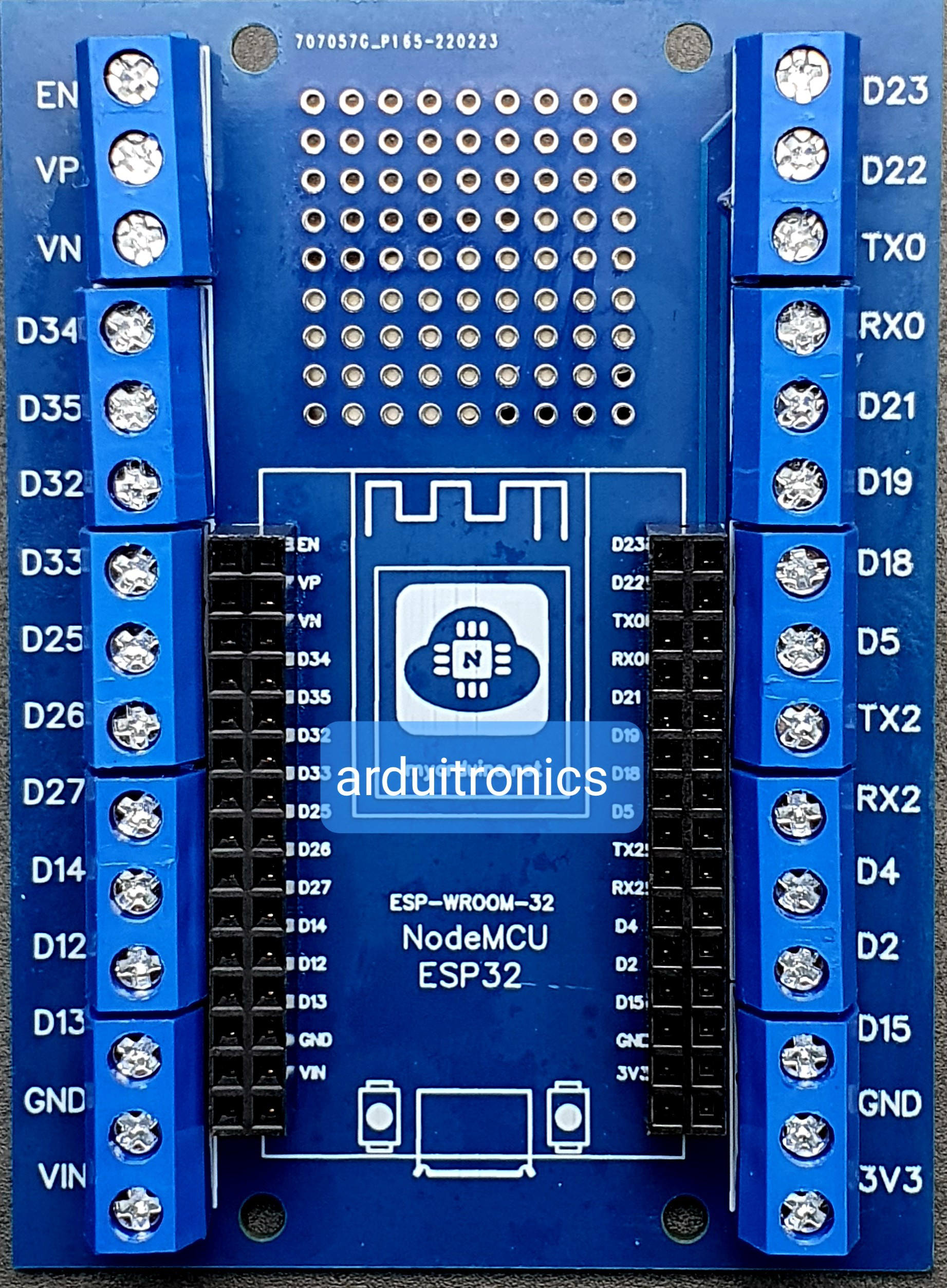
The Screw Shield ESP32 is an accessory designed to simplify prototyping and assembly with the ESP32 microcontroller. It features screw terminals that allow for secure and reliable connections of wires and components without the need for soldering. This shield is particularly useful for projects requiring robust and stable wiring, such as industrial automation, IoT applications, and educational setups.
Explore Projects Built with screw shield esp32
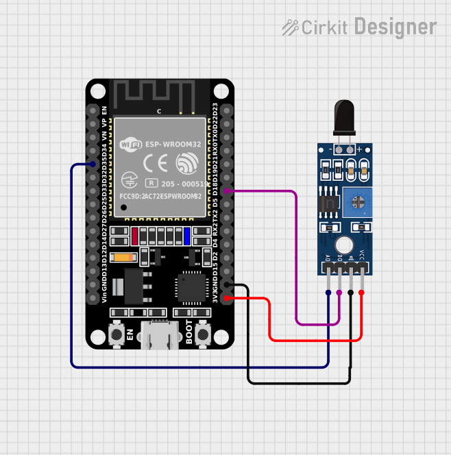
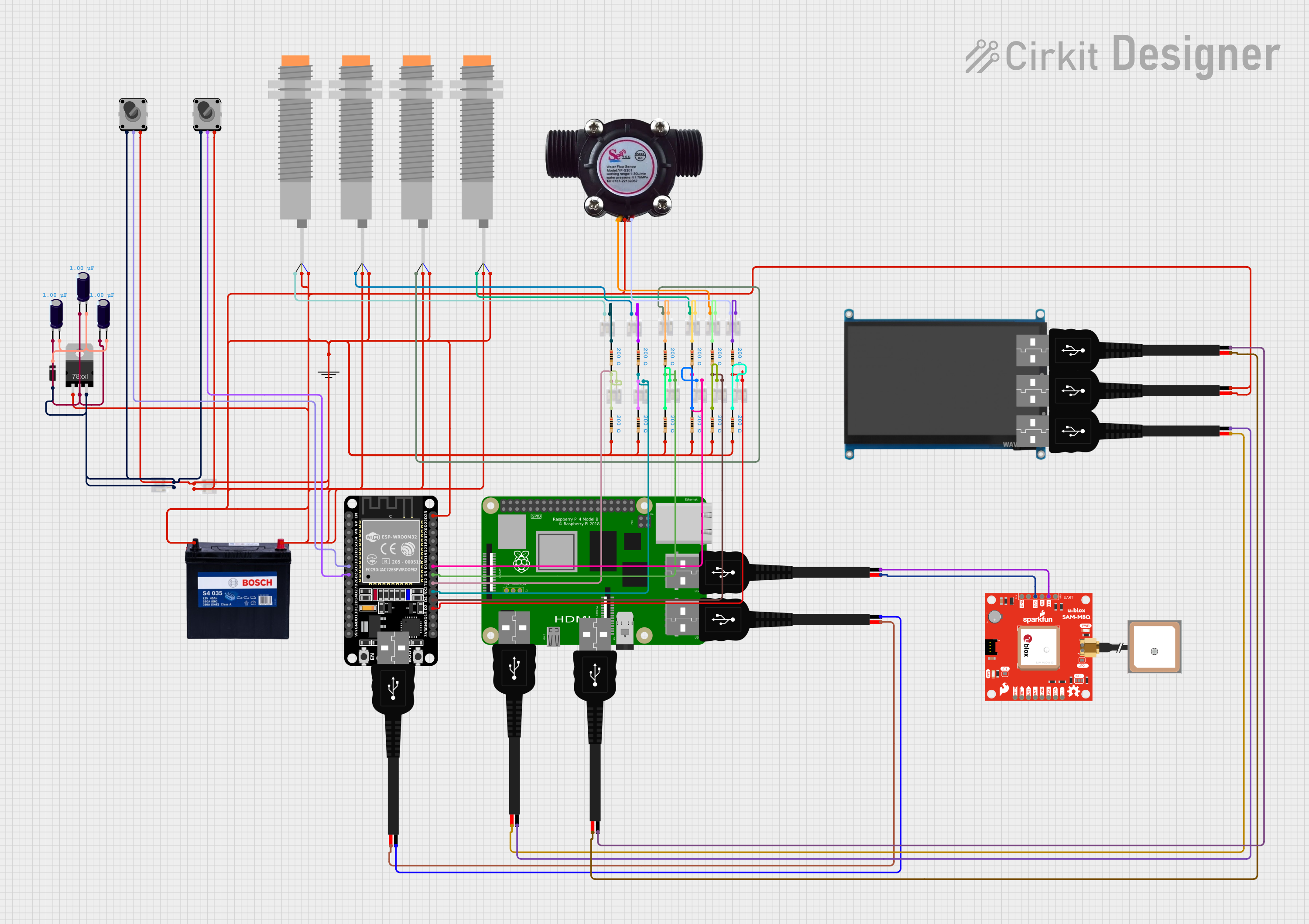
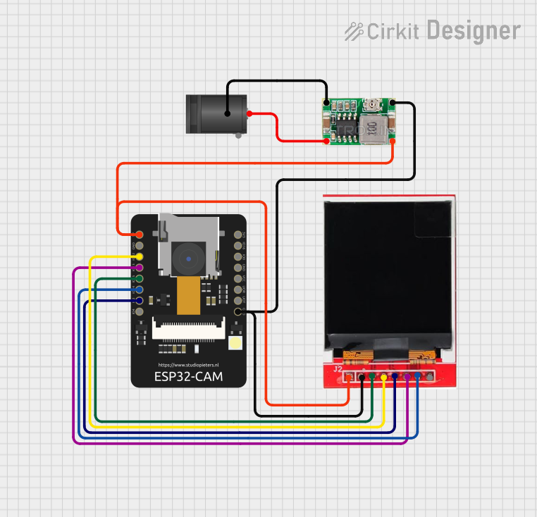
Explore Projects Built with screw shield esp32
Common Applications and Use Cases
- IoT Projects: Securely connect sensors, actuators, and other peripherals.
- Industrial Automation: Reliable wiring for control systems and monitoring devices.
- Prototyping: Quick and easy assembly of circuits for testing and development.
- Educational Projects: Simplifies wiring for students and beginners.
Technical Specifications
The Screw Shield ESP32 is designed to fit seamlessly with the ESP32 microcontroller, providing easy access to all GPIO pins via screw terminals.
Key Technical Details
| Parameter | Specification |
|---|---|
| Compatible Microcontroller | ESP32 |
| Operating Voltage | 3.3V (matches ESP32 voltage levels) |
| Maximum Current per Pin | 500mA |
| Terminal Type | Screw terminals |
| Terminal Pitch | 3.5mm |
| Dimensions | Matches ESP32 development board size |
| Material | PCB with durable screw terminals |
Pin Configuration and Descriptions
The Screw Shield ESP32 provides screw terminal access to all ESP32 GPIO pins. Below is the pin mapping:
| Screw Terminal | ESP32 Pin | Description |
|---|---|---|
| D0 | GPIO0 | General-purpose I/O |
| D1 | GPIO1 | General-purpose I/O |
| D2 | GPIO2 | General-purpose I/O |
| D3 | GPIO3 | General-purpose I/O |
| ... | ... | ... (follows ESP32 pinout) |
| 3V3 | 3.3V | Power supply |
| GND | GND | Ground |
Note: Ensure you refer to the ESP32 datasheet for specific GPIO capabilities (e.g., ADC, PWM, I2C, etc.).
Usage Instructions
How to Use the Screw Shield ESP32 in a Circuit
- Attach the Shield: Place the Screw Shield onto the ESP32 development board, ensuring proper alignment of the pins.
- Connect Wires: Insert wires into the screw terminals and tighten the screws to secure the connections.
- Power the ESP32: Provide power to the ESP32 via USB or an external power source.
- Connect Peripherals: Use the screw terminals to connect sensors, actuators, or other components to the corresponding GPIO pins.
Important Considerations and Best Practices
- Wire Gauge: Use wires with a gauge compatible with the screw terminals (typically 22-26 AWG).
- Tighten Securely: Ensure screws are tightened properly to avoid loose connections.
- Avoid Overloading: Do not exceed the maximum current rating of 500mA per pin.
- Check Pin Functions: Verify the functionality of each GPIO pin (e.g., ADC, PWM) before connecting components.
- Static Protection: Handle the ESP32 and shield with care to avoid damage from static electricity.
Example: Connecting an LED to the Screw Shield ESP32
Below is an example of how to connect an LED to GPIO2 using the Screw Shield ESP32 and control it with an Arduino sketch.
Circuit Setup
- Connect the positive leg of the LED to the screw terminal corresponding to GPIO2.
- Connect the negative leg of the LED to the GND screw terminal.
- Optionally, use a 220-ohm resistor in series with the LED to limit current.
Arduino Code
// Example code to blink an LED connected to GPIO2 via the Screw Shield ESP32

#define LED_PIN 2  // Define the GPIO pin connected to the LED

void setup() {
  pinMode(LED_PIN, OUTPUT);  // Set GPIO2 as an output pin
}

void loop() {
  digitalWrite(LED_PIN, HIGH);  // Turn the LED on
  delay(1000);                  // Wait for 1 second
  digitalWrite(LED_PIN, LOW);   // Turn the LED off
  delay(1000);                  // Wait for 1 second
}
Troubleshooting and FAQs
Common Issues and Solutions
Loose Connections
- Issue: Wires are not securely connected to the screw terminals.
- Solution: Ensure the screws are tightened properly and the wires are stripped to the correct length.
ESP32 Not Powering On
- Issue: The ESP32 does not turn on when the shield is attached.
- Solution: Verify that the shield is properly aligned with the ESP32 pins and that the power source is sufficient.
Peripheral Not Responding
- Issue: Connected sensors or actuators are not functioning.
- Solution: Double-check the GPIO pin assignments and ensure the components are compatible with the ESP32's voltage levels.
Overheating
- Issue: The ESP32 or shield becomes hot during operation.
- Solution: Check for short circuits or excessive current draw on any GPIO pin.
FAQs
Q: Can I use this shield with other microcontrollers?
A: No, the Screw Shield ESP32 is specifically designed for the ESP32 pinout and may not be compatible with other microcontrollers.Q: What is the maximum wire size supported by the screw terminals?
A: The screw terminals typically support wires in the range of 22-26 AWG.Q: Can I use this shield for high-power applications?
A: No, the shield is designed for low-power applications with a maximum current rating of 500mA per pin.Q: Is the shield stackable with other ESP32 shields?
A: Yes, as long as the other shields do not interfere with the screw terminals or GPIO pin access.
This concludes the documentation for the Screw Shield ESP32.