How to Use CABLE AC 3 PIN: Examples, Pinouts, and Specs
Introduction
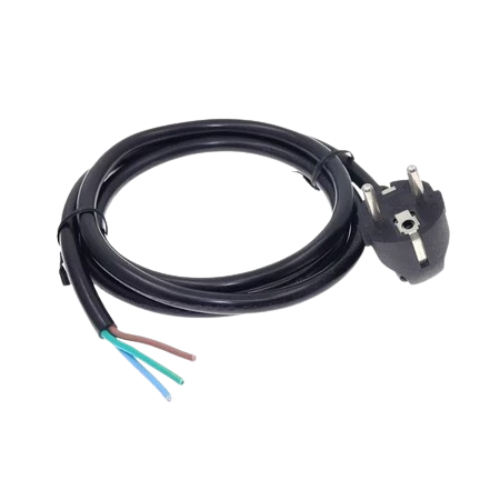
The CABLE AC 3 PIN is a widely used electrical component designed for connecting devices to an alternating current (AC) power source. It features three pins: live, neutral, and ground, ensuring safe and reliable power delivery. This cable is commonly used in household appliances, computers, power tools, and other electronic devices requiring a grounded connection for safety.
Explore Projects Built with CABLE AC 3 PIN

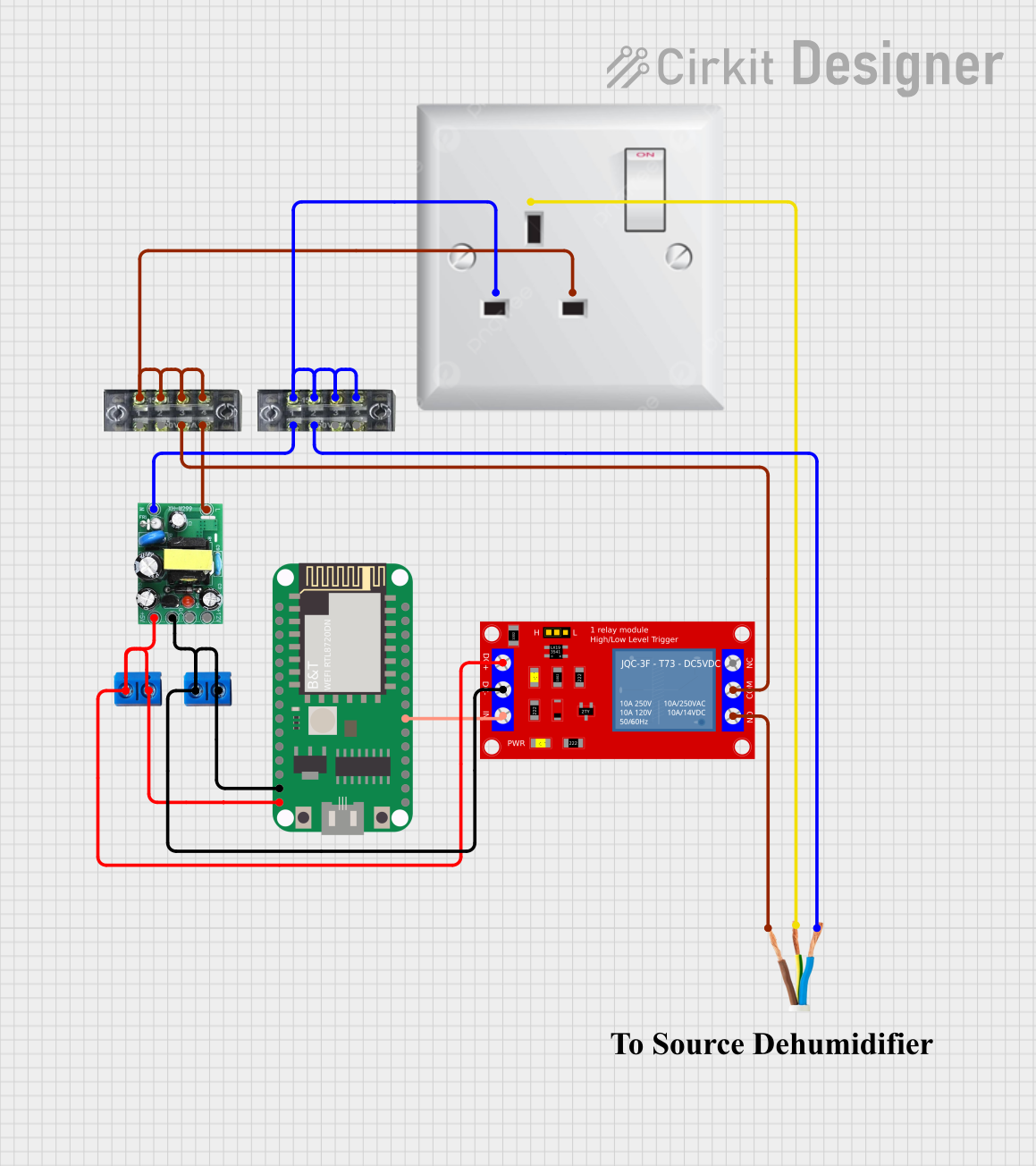

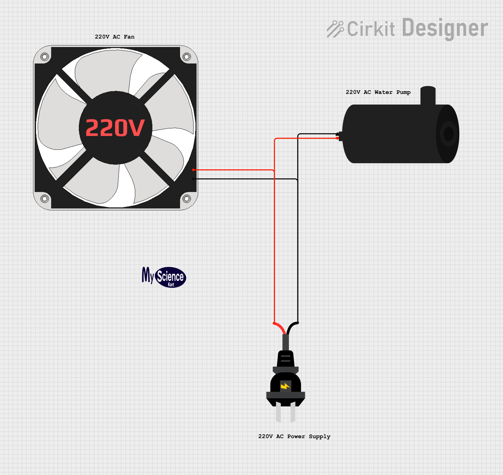
Explore Projects Built with CABLE AC 3 PIN
Common Applications and Use Cases
- Powering desktop computers, monitors, and printers
- Connecting household appliances such as microwaves and refrigerators
- Supplying power to industrial equipment and power tools
- Ensuring electrical safety through proper grounding in sensitive devices
Technical Specifications
Key Technical Details
| Parameter | Specification |
|---|---|
| Voltage Rating | 110V - 250V AC |
| Current Rating | 6A - 16A (varies by cable type) |
| Frequency | 50Hz / 60Hz |
| Cable Length | Typically 1m to 3m (varies by model) |
| Connector Type | IEC 60320 C13 (common for devices) |
| Pin Configuration | Live, Neutral, Ground |
| Insulation Material | PVC or Rubber |
| Operating Temperature | -10°C to 70°C |
| Safety Standards | Compliant with IEC and UL standards |
Pin Configuration and Descriptions
| Pin Name | Description | Wire Color (Standard) |
|---|---|---|
| Live (L) | Carries the active current from the power source | Brown |
| Neutral (N) | Returns current to the power source | Blue |
| Ground (G) | Provides a safety path for fault currents | Green/Yellow |
Usage Instructions
How to Use the Component in a Circuit
- Inspect the Cable: Before use, ensure the cable is free from visible damage, such as cuts or exposed wires.
- Connect to Device: Plug the IEC connector (C13 or similar) into the device's power input port.
- Connect to Power Source: Insert the three-pin plug into a compatible AC wall socket.
- Verify Grounding: Ensure the wall socket has a proper ground connection to avoid electrical hazards.
- Power On: Turn on the device and confirm it operates as expected.
Important Considerations and Best Practices
- Check Compatibility: Ensure the cable's voltage and current ratings match the device's requirements.
- Avoid Overloading: Do not use the cable with devices that exceed its current rating.
- Inspect Regularly: Periodically check for wear and tear, especially near the connectors.
- Use in Dry Environments: Avoid using the cable in wet or humid conditions to prevent electrical shocks.
- Proper Grounding: Always use a grounded outlet to ensure safety and prevent damage to sensitive electronics.
Example: Connecting to an Arduino UNO
While the CABLE AC 3 PIN itself does not directly interface with an Arduino UNO, it can be used to power an external power supply or adapter that provides DC power to the Arduino. Below is an example of how to use the cable indirectly:
- Connect the CABLE AC 3 PIN to an AC-to-DC adapter.
- Plug the adapter's DC output into the Arduino UNO's power jack.
- Use the following Arduino code to verify the board is powered and functioning:
// Simple LED Blink Test to Verify Arduino Power
// Connect an LED to pin 13 with a resistor in series

void setup() {
  pinMode(13, OUTPUT); // Set pin 13 as an output
}

void loop() {
  digitalWrite(13, HIGH); // Turn the LED on
  delay(1000);            // Wait for 1 second
  digitalWrite(13, LOW);  // Turn the LED off
  delay(1000);            // Wait for 1 second
}
Troubleshooting and FAQs
Common Issues Users Might Face
Cable Does Not Fit the Device or Socket:
- Solution: Verify the connector type (e.g., IEC C13) and ensure compatibility with the device and wall socket.
Device Does Not Power On:
- Solution: Check the wall socket for power. Inspect the cable for damage or loose connections.
Overheating of the Cable:
- Solution: Ensure the connected device does not exceed the cable's current rating. Replace the cable if insulation appears damaged.
Electrical Shocks or Sparks:
- Solution: Stop using the cable immediately. Inspect for exposed wires or damaged insulation. Ensure the wall socket is properly grounded.
Tips for Troubleshooting
- Use a multimeter to check continuity between the pins and wires.
- Test the wall socket with another device to confirm it is supplying power.
- Replace the cable if it shows signs of wear, such as frayed wires or loose connectors.
By following this documentation, users can safely and effectively utilize the CABLE AC 3 PIN for powering their devices while ensuring proper operation and safety.