
How to Use JUMPER-3-OLD: Examples, Pinouts, and Specs
 Design with JUMPER-3-OLD in Cirkit Designer
Introduction
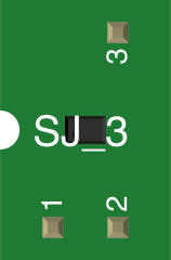
The JUMPER-3-OLD is a short length of conductive material, typically encased in a plastic housing, used to connect two points in a circuit. This component is commonly employed to configure hardware settings, enable or disable specific features, or bridge connections on printed circuit boards (PCBs). The "3" in its name suggests it is designed for a specific 3-pin configuration, while "OLD" indicates it may be an older version or model, potentially with legacy compatibility.
Explore Projects Built with JUMPER-3-OLD
 Open Project in Cirkit Designer
 Open Project in Cirkit Designer
 Open Project in Cirkit Designer
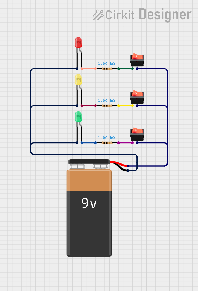 Open Project in Cirkit Designer
Explore Projects Built with JUMPER-3-OLD
Open Project in Cirkit DesignerOpen Project in Cirkit DesignerOpen Project in Cirkit DesignerOpen Project in Cirkit DesignerCommon Applications and Use Cases
- Hardware Configuration: Used to set modes or options on motherboards, hard drives, or other electronic devices.
- Circuit Testing: Temporarily bridges connections for debugging or testing purposes.
- Prototyping: Quickly connects or disconnects parts of a circuit during development.
- Legacy Systems: Ideal for older devices or systems requiring specific jumper configurations.
Technical Specifications
Key Technical Details
- Material: Conductive metal (e.g., copper or brass) with a plastic insulating housing.
- Pin Compatibility: Designed for 3-pin headers with a standard 2.54mm (0.1 inch) pitch.
- Current Rating: Typically supports up to 2A.
- Voltage Rating: Up to 50V DC.
- Durability: Rated for approximately 100 insertion/removal cycles.
Pin Configuration and Descriptions
The JUMPER-3-OLD is designed to connect two adjacent pins on a 3-pin header. Below is the typical configuration:
| Pin Number | Description |
|---|---|
| Pin 1 | First connection point (e.g., VCC) |
| Pin 2 | Middle pin (common connection point) |
| Pin 3 | Third connection point (e.g., GND) |
Note: The jumper bridges either Pin 1 and Pin 2 or Pin 2 and Pin 3, depending on its placement.
Usage Instructions
How to Use the JUMPER-3-OLD in a Circuit
- Identify the Header Pins: Locate the 3-pin header on your PCB where the jumper will be used.
- Determine the Desired Configuration: Refer to the device's manual or schematic to understand which pins need to be connected.
- Place the Jumper: Align the JUMPER-3-OLD with the desired pins and gently push it down until it is securely seated.
- To connect Pin 1 and Pin 2, place the jumper over these two pins.
- To connect Pin 2 and Pin 3, shift the jumper to cover these pins instead.
- Verify the Connection: Ensure the jumper is firmly in place and making proper contact.
Important Considerations and Best Practices
- Avoid Overcurrent: Do not exceed the current rating of 2A to prevent overheating or damage.
- Check Compatibility: Ensure the jumper is compatible with the pin pitch (2.54mm) of your header.
- Handle with Care: Repeated insertion and removal can wear out the jumper or the header pins.
- Document Configurations: Keep track of jumper settings to avoid confusion during troubleshooting.
Example: Using JUMPER-3-OLD with an Arduino UNO
While the JUMPER-3-OLD is not directly programmable, it can be used to configure hardware connected to an Arduino UNO. For example, it can enable or disable specific features on a shield or module.
Here’s an example of how to use a jumper to configure a module and read its state in Arduino code:
// Example: Reading the state of a jumper-configured module
const int jumperPin = 7; // Pin connected to the module's output

void setup() {
  pinMode(jumperPin, INPUT_PULLUP); // Configure pin as input with pull-up resistor
  Serial.begin(9600); // Initialize serial communication
}

void loop() {
  int jumperState = digitalRead(jumperPin); // Read the state of the jumper
  if (jumperState == LOW) {
    // Jumper is connecting the circuit (active state)
    Serial.println("Jumper is connected.");
  } else {
    // Jumper is not connecting the circuit (inactive state)
    Serial.println("Jumper is disconnected.");
  }
  delay(500); // Wait for 500ms before reading again
}
Note: This example assumes the jumper is used to configure a module that outputs a HIGH or LOW signal based on its state.
Troubleshooting and FAQs
Common Issues Users Might Face
- Loose Connection: The jumper may not make proper contact with the pins.
- Solution: Ensure the jumper is fully seated and aligned with the pins.
- Incorrect Configuration: The jumper is placed on the wrong pins.
- Solution: Double-check the device's manual or schematic for the correct placement.
- Worn-Out Jumper: After repeated use, the jumper may lose its grip or conductivity.
- Solution: Replace the jumper with a new one if it no longer fits securely or conducts properly.
- Overcurrent Damage: Exceeding the current rating can cause overheating or failure.
- Solution: Verify the current requirements of your circuit and ensure they are within the jumper's specifications.
FAQs
Q: Can I use the JUMPER-3-OLD on a 2-pin header?
A: Yes, but it will only connect the two pins and leave the third pin unused.
Q: Is the JUMPER-3-OLD compatible with modern devices?
A: While it is designed for older systems, it can still be used with modern devices as long as the pin pitch and ratings match.
Q: How do I know if the jumper is working?
A: Use a multimeter to check continuity between the connected pins. If there is continuity, the jumper is functioning correctly.
Q: Can I use multiple jumpers on the same header?
A: Yes, as long as the header has enough pins and the jumpers do not interfere with each other.
By following this documentation, you can effectively use the JUMPER-3-OLD in your projects and troubleshoot any issues that arise.