Cirkit Designer Logo
Cirkit Designer
Your all-in-one circuit design IDE
Home / 
Component Documentation

How to Use Motor Driver Expansion Board Bottom side: Examples, Pinouts, and Specs

Image of Motor Driver Expansion Board Bottom side
Cirkit Designer LogoDesign with Motor Driver Expansion Board Bottom side in Cirkit Designer

Introduction

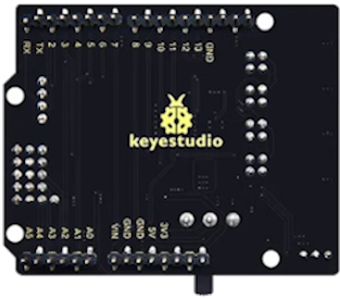
The Keyestudio 8833 Motor Driver Expansion Board is an electronic module designed to facilitate the control of motors in various applications such as robotics, automation, and custom projects. It is compatible with microcontroller platforms like Arduino UNO, making it an ideal choice for hobbyists and professionals alike. The board is capable of driving multiple motors simultaneously and offers features such as speed control and direction control.

Explore Projects Built with Motor Driver Expansion Board Bottom side

Use Cirkit Designer to design, explore, and prototype these projects online. Some projects support real-time simulation. Click "Open Project" to start designing instantly!
Arduino-Powered Battery-Operated Dual DC Motor Control System
Image of Motor control- Arduino nano + expansion board + L298N: A project utilizing Motor Driver Expansion Board Bottom side in a practical application
This circuit uses an Arduino Expansion Board to control two DC Mini Metal Gear Motors via an L298N DC motor driver. The motors are powered by a 2200mAh LiPo battery, and the Arduino sends control signals to the motor driver to manage the direction and speed of the motors.
Cirkit Designer LogoOpen Project in Cirkit Designer
Stepper Motor Control System with TB6600 Driver and Relay Integration
Image of Copy of Copy of Copy of PLC-Based Step Motor Speed and Direction Control System: A project utilizing Motor Driver Expansion Board Bottom side in a practical application
This circuit controls a bipolar stepper motor using a tb6600 micro stepping motor driver and a DKC-1A stepper motor controller. It includes a 24VDC power supply, a 4-channel relay module, and panel mount banana sockets for power connections. The motor driver and controller are interconnected to manage the motor's direction and pulse signals.
Cirkit Designer LogoOpen Project in Cirkit Designer
ESP32-Controlled Dual Motor Driver with Optical Encoder Feedback
Image of Copy of Mobile Robot System with Speed and Position Control Using ESP32: A project utilizing Motor Driver Expansion Board Bottom side in a practical application
This circuit is designed to control two DC motors using an L298N Dual Motor Driver Module, which receives PWM control signals from an ESP32 microcontroller. The motors' rotational movement can be monitored by two Optical Encoder Sensor Modules connected to the ESP32. Power is supplied by a 4 x AAA battery mount, with the battery's positive terminal connected to the motor driver's 12V input and the negative terminal to the common ground.
Cirkit Designer LogoOpen Project in Cirkit Designer
Stepper Motor Control System with TB6600 Driver and DKC-1A Controller
Image of Copy of Copy of PLC-Based Step Motor Speed and Direction Control System: A project utilizing Motor Driver Expansion Board Bottom side in a practical application
This circuit controls a bipolar stepper motor using a tb6600 micro stepping motor driver and a DKC-1A stepper motor controller. The system is powered by a 24VDC power supply and includes a relay module for additional control functionalities.
Cirkit Designer LogoOpen Project in Cirkit Designer

Explore Projects Built with Motor Driver Expansion Board Bottom side

Use Cirkit Designer to design, explore, and prototype these projects online. Some projects support real-time simulation. Click "Open Project" to start designing instantly!
Image of Motor control- Arduino nano + expansion board + L298N: A project utilizing Motor Driver Expansion Board Bottom side in a practical application
Arduino-Powered Battery-Operated Dual DC Motor Control System
This circuit uses an Arduino Expansion Board to control two DC Mini Metal Gear Motors via an L298N DC motor driver. The motors are powered by a 2200mAh LiPo battery, and the Arduino sends control signals to the motor driver to manage the direction and speed of the motors.
Cirkit Designer LogoOpen Project in Cirkit Designer
Image of Copy of Copy of Copy of PLC-Based Step Motor Speed and Direction Control System: A project utilizing Motor Driver Expansion Board Bottom side in a practical application
Stepper Motor Control System with TB6600 Driver and Relay Integration
This circuit controls a bipolar stepper motor using a tb6600 micro stepping motor driver and a DKC-1A stepper motor controller. It includes a 24VDC power supply, a 4-channel relay module, and panel mount banana sockets for power connections. The motor driver and controller are interconnected to manage the motor's direction and pulse signals.
Cirkit Designer LogoOpen Project in Cirkit Designer
Image of Copy of Mobile Robot System with Speed and Position Control Using ESP32: A project utilizing Motor Driver Expansion Board Bottom side in a practical application
ESP32-Controlled Dual Motor Driver with Optical Encoder Feedback
This circuit is designed to control two DC motors using an L298N Dual Motor Driver Module, which receives PWM control signals from an ESP32 microcontroller. The motors' rotational movement can be monitored by two Optical Encoder Sensor Modules connected to the ESP32. Power is supplied by a 4 x AAA battery mount, with the battery's positive terminal connected to the motor driver's 12V input and the negative terminal to the common ground.
Cirkit Designer LogoOpen Project in Cirkit Designer
Image of Copy of Copy of PLC-Based Step Motor Speed and Direction Control System: A project utilizing Motor Driver Expansion Board Bottom side in a practical application
Stepper Motor Control System with TB6600 Driver and DKC-1A Controller
This circuit controls a bipolar stepper motor using a tb6600 micro stepping motor driver and a DKC-1A stepper motor controller. The system is powered by a 24VDC power supply and includes a relay module for additional control functionalities.
Cirkit Designer LogoOpen Project in Cirkit Designer

Common Applications and Use Cases

  • Robotics: Driving wheels or tracks on robotic vehicles.
  • Automation: Controlling conveyor belts, actuators, or other machinery.
  • Educational Projects: Teaching motor control principles in STEM education.
  • DIY Projects: Custom builds requiring motor control, such as automated plant watering systems.

Technical Specifications

Key Technical Details

  • Operating Voltage: 6V to 12V
  • Continuous Current per Channel: 1.2A
  • Peak Current per Channel: 3.2A (for a few milliseconds)
  • Logic Control Voltage: 5V (from Arduino UNO)
  • Motor Driver: Dual H-Bridge configuration

Pin Configuration and Descriptions

Pin Number Pin Name Description
1 VM Motor power supply input (6V-12V)
2 GND Ground connection
3 V5 5V output (from Arduino UNO)
4 D2 Direction control for Motor A
5 D3 Speed control for Motor A (PWM)
6 D4 Direction control for Motor B
7 D5 Speed control for Motor B (PWM)
8 D6 Brake for Motor A
9 D7 Brake for Motor B
10 A+ Motor A output positive
11 A- Motor A output negative
12 B+ Motor B output positive
13 B- Motor B output negative

Usage Instructions

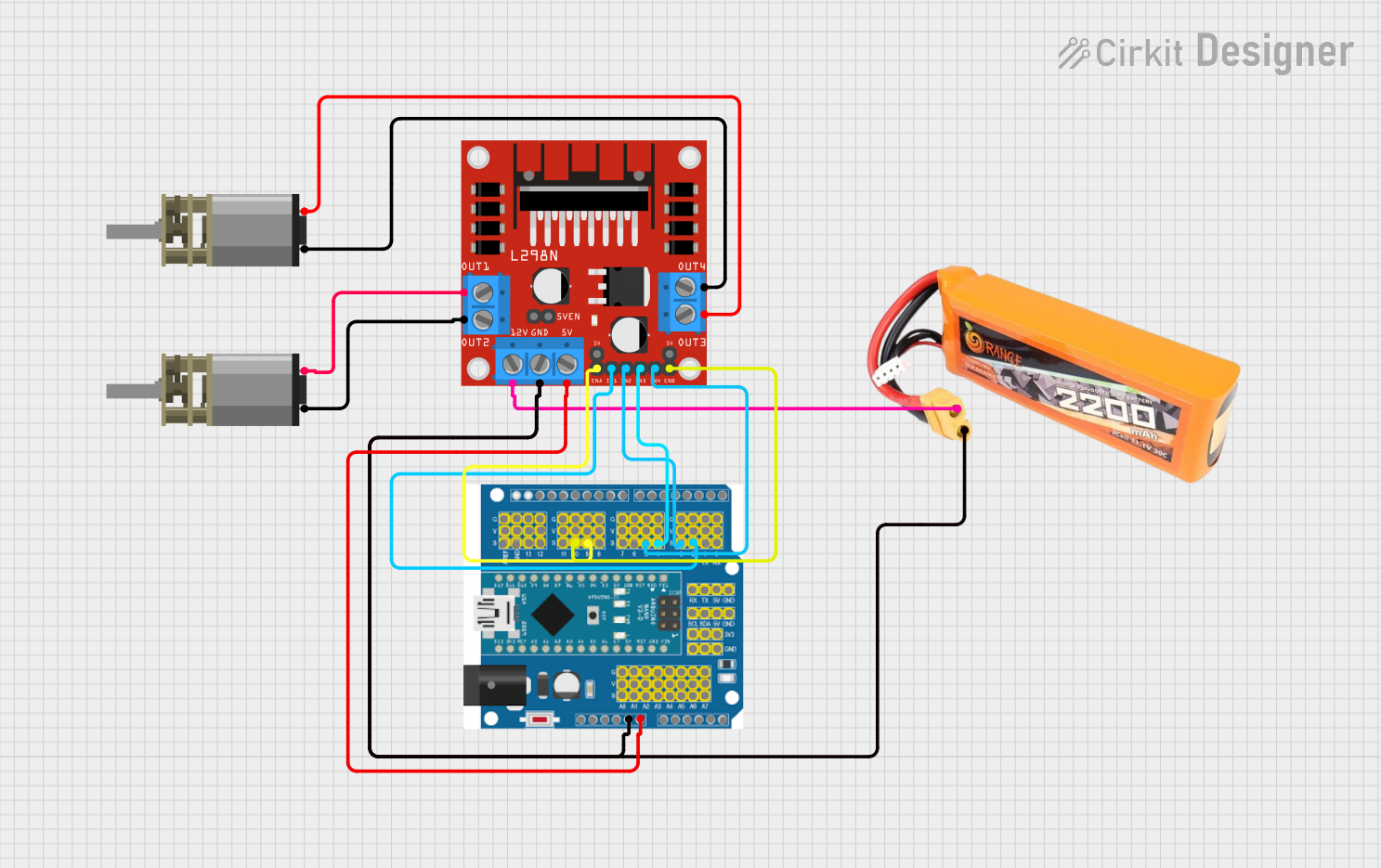
How to Use the Component in a Circuit

  1. Connect the VM pin to your motor power supply (6V-12V).
  2. Connect the GND pin to the ground of your power supply and Arduino.
  3. Connect the V5 pin to the 5V output on the Arduino if additional 5V supply is needed.
  4. Connect the D2-D7 pins to the corresponding digital pins on the Arduino for control signals.
  5. Connect the motor terminals to the A+/A- and B+/B- outputs for Motor A and Motor B, respectively.

Important Considerations and Best Practices

  • Ensure the power supply voltage and current do not exceed the board's ratings.
  • Use PWM signals on D3 and D5 for speed control.
  • Use digital HIGH/LOW signals on D2 and D4 to set the direction of the motors.
  • Utilize D6 and D7 for braking functionality.
  • Always double-check wiring to prevent short circuits or incorrect connections.
  • Implement proper decoupling techniques to minimize noise and voltage spikes.

Troubleshooting and FAQs

Common Issues

  • Motor not running: Check power supply connections and ensure the control signals are being sent from the Arduino.
  • Overheating: Ensure the current draw is within the board's limits and provide adequate cooling if necessary.
  • Inconsistent motor speed: Verify PWM signal integrity and check for any loose connections.

Solutions and Tips for Troubleshooting

  • Double-check all connections, especially power and ground.
  • Use a multimeter to verify voltage levels at various points in the circuit.
  • Ensure the Arduino code is correctly generating PWM and digital control signals.
  • If the board is not functioning, disconnect all power and inspect for any signs of damage or burnt components.

FAQs

Q: Can I control stepper motors with this board? A: No, this board is designed for DC motors. Stepper motors require a different type of driver.

Q: What is the maximum number of motors I can control with this board? A: You can control up to two motors independently with this board.

Q: Can I use this board without an Arduino? A: While designed for use with an Arduino, any microcontroller capable of providing the correct logic signals can be used.

Example Arduino Code

// Example code to control Motor A on the Keyestudio 8833 Motor Driver Expansion Board

const int motorASpeedPin = 3; // D3 for PWM speed control
const int motorADirectionPin = 2; // D2 for direction control
const int motorABrakePin = 6; // D6 for brake control

void setup() {
  pinMode(motorASpeedPin, OUTPUT);
  pinMode(motorADirectionPin, OUTPUT);
  pinMode(motorABrakePin, OUTPUT);
}

void loop() {
  // Set motor A direction to forward
  digitalWrite(motorADirectionPin, HIGH);
  
  // Disable motor A brake
  digitalWrite(motorABrakePin, LOW);
  
  // Ramp up the speed of motor A
  for (int speed = 0; speed <= 255; speed++) {
    analogWrite(motorASpeedPin, speed);
    delay(10);
  }
  
  // Engage motor A brake
  digitalWrite(motorABrakePin, HIGH);
  delay(1000);
  
  // Repeat the process for reverse direction and braking
}

Remember to keep the code comments concise and within the 80 character line length limit. This example demonstrates basic motor control including direction, speed, and braking.