How to Use GY-271M: Examples, Pinouts, and Specs

 Design with GY-271M in Cirkit Designer
Introduction
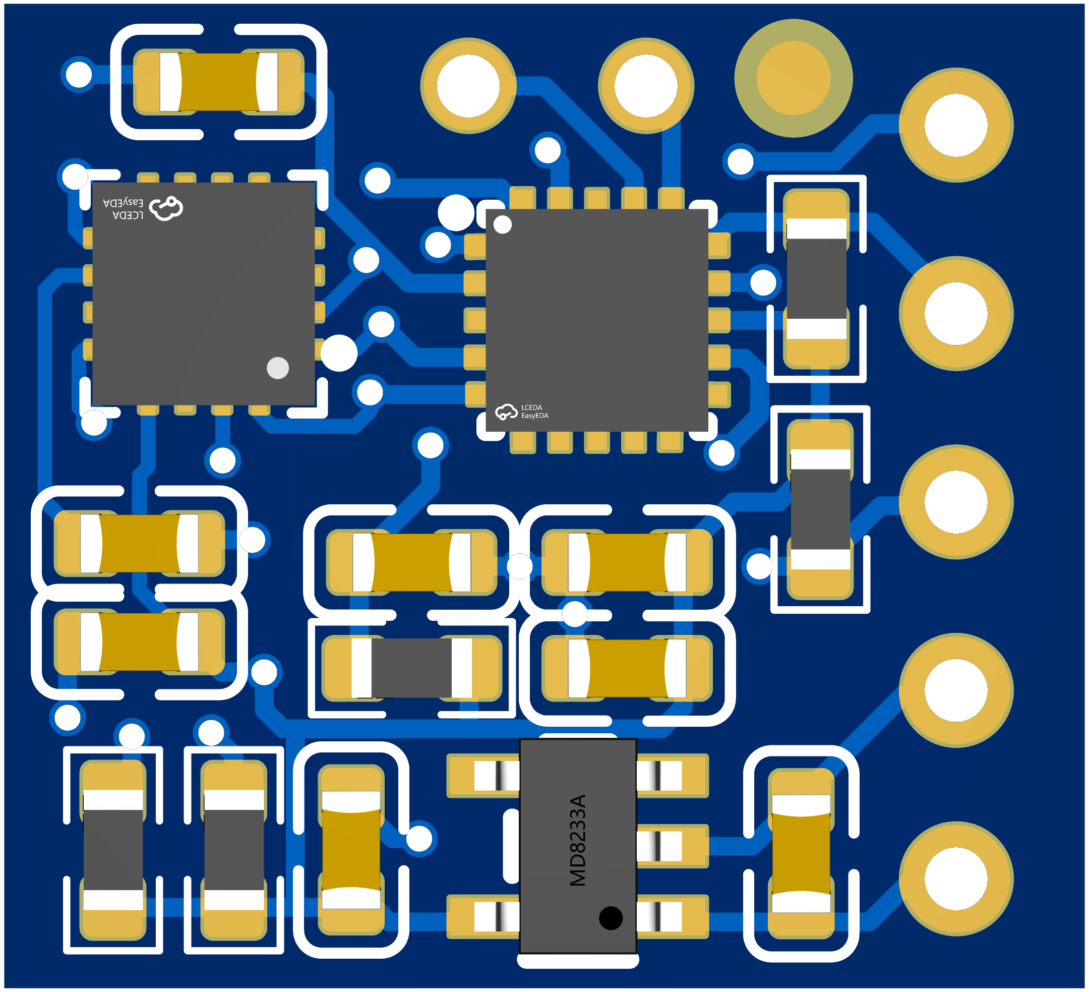
The GY-271M is a digital compass module designed for precise magnetic field measurement and orientation detection. It is built around the HMC5883L sensor, a 3-axis magnetometer capable of detecting magnetic fields in the X, Y, and Z axes. Manufactured by 宏维微 (part ID: HW-948), this module is widely used in navigation, robotics, and other applications requiring accurate heading information.
Explore Projects Built with GY-271M

 Open Project in Cirkit Designer
 Open Project in Cirkit Designer
 Open Project in Cirkit Designer
 Open Project in Cirkit Designer
Explore Projects Built with GY-271M

 Open Project in Cirkit Designer
 Open Project in Cirkit Designer
 Open Project in Cirkit Designer
 Open Project in Cirkit Designer
Common Applications
- Navigation systems (e.g., GPS-assisted heading determination)
- Robotics for orientation and pathfinding
- Drone stabilization and control
- Handheld electronic compasses
- Augmented reality (AR) devices for directional awareness
Technical Specifications
The GY-271M module is compact and easy to integrate into various projects. Below are its key technical details:
Key Specifications
| Parameter | Value |
|---|---|
| Sensor | HMC5883L |
| Operating Voltage | 3.3V to 5V |
| Communication Protocol | I2C |
| Measurement Range | ±1.3 to ±8 Gauss |
| Resolution | 0.73 milliGauss (at ±1.3 Gauss) |
| Operating Temperature | -40°C to +85°C |
| Dimensions | 14mm x 13mm |
Pin Configuration
The GY-271M module has a 4-pin interface for I2C communication. Below is the pinout:
| Pin Name | Description |
|---|---|
| VCC | Power supply input (3.3V to 5V) |
| GND | Ground |
| SDA | I2C data line |
| SCL | I2C clock line |
Usage Instructions
The GY-271M module is straightforward to use in a circuit, especially with microcontrollers like the Arduino UNO. Follow the steps below to integrate and use the module:
Connecting the GY-271M to an Arduino UNO
- Power the Module: Connect the
VCCpin of the GY-271M to the 5V pin on the Arduino UNO. Connect theGNDpin to the Arduino's GND. - I2C Communication: Connect the
SDApin of the module to the Arduino's A4 pin and theSCLpin to the A5 pin. (For newer Arduino boards like the Mega or Nano, refer to their specific I2C pinout.) - Install Required Libraries: Download and install the "Adafruit HMC5883L" library or any compatible library for the HMC5883L sensor in the Arduino IDE.
Sample Arduino Code
The following code demonstrates how to read heading data from the GY-271M module:
#include <Wire.h>
#include <Adafruit_Sensor.h>
#include <Adafruit_HMC5883_U.h>

// Create an instance of the HMC5883L sensor
Adafruit_HMC5883_Unified mag = Adafruit_HMC5883_Unified(12345);

void setup() {
  Serial.begin(9600); // Initialize serial communication
  Serial.println("GY-271M Compass Module Test");

  // Initialize the sensor
  if (!mag.begin()) {
    Serial.println("Could not find a valid HMC5883L sensor, check wiring!");
    while (1); // Halt execution if sensor initialization fails
  }
}

void loop() {
  sensors_event_t event;
  mag.getEvent(&event); // Get magnetic field data

  // Calculate heading in degrees
  float heading = atan2(event.magnetic.y, event.magnetic.x);
  heading = heading * 180 / PI; // Convert radians to degrees

  // Normalize heading to 0-360 degrees
  if (heading < 0) {
    heading += 360;
  }

  // Print heading to the Serial Monitor
  Serial.print("Heading: ");
  Serial.print(heading);
  Serial.println("°");

  delay(500); // Wait 500ms before the next reading
}
Important Considerations
- Magnetic Interference: Avoid placing the module near ferromagnetic materials or electronic devices that generate strong magnetic fields, as they can distort readings.
- Calibration: For accurate results, calibrate the module by rotating it in all directions to map the magnetic field.
- I2C Address: The default I2C address of the HMC5883L is
0x1E. Ensure no other devices on the I2C bus share this address.
Troubleshooting and FAQs
Common Issues and Solutions
No Data or Incorrect Readings
- Cause: Improper wiring or loose connections.
- Solution: Double-check all connections, ensuring SDA and SCL are correctly connected to the Arduino.
Sensor Not Detected
- Cause: Incorrect I2C address or library not installed.
- Solution: Verify the I2C address (
0x1E) and ensure the required library is installed in the Arduino IDE.
Inconsistent Heading Values
- Cause: Magnetic interference or lack of calibration.
- Solution: Move the module away from interference sources and perform a calibration routine.
Arduino Freezes During Execution
- Cause: I2C communication issue.
- Solution: Check pull-up resistors on the I2C lines (if required) and ensure proper wiring.
FAQs
Q: Can the GY-271M work with 3.3V microcontrollers?
A: Yes, the module supports both 3.3V and 5V logic levels, making it compatible with a wide range of microcontrollers.
Q: How do I calibrate the GY-271M?
A: Rotate the module in all directions while collecting data. Use the readings to calculate offsets and scale factors for each axis.
Q: What is the maximum range of the GY-271M?
A: The module can measure magnetic fields up to ±8 Gauss, but the default range is ±1.3 Gauss for higher resolution.
Q: Can I use the GY-271M for tilt compensation?
A: The GY-271M itself does not provide tilt compensation. You will need an accelerometer or gyroscope to achieve this functionality.
By following this documentation, you can effectively integrate and use the GY-271M module in your projects.