How to Use GY-85: Examples, Pinouts, and Specs
Introduction
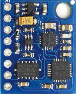
The GY-85 is a 9-axis motion sensor module that integrates an accelerometer, gyroscope, and magnetometer into a single compact board. This module is widely used for applications requiring precise orientation and motion tracking, such as robotics, drones, smartphones, and gaming devices. Its ability to measure acceleration, angular velocity, and magnetic field strength makes it a versatile choice for projects involving motion sensing and navigation.
Explore Projects Built with GY-85


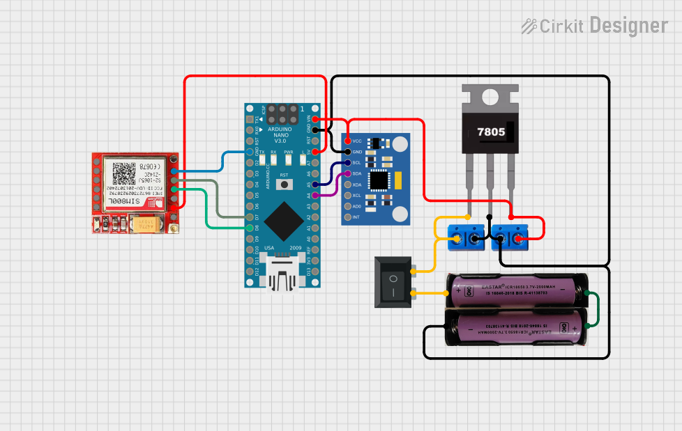
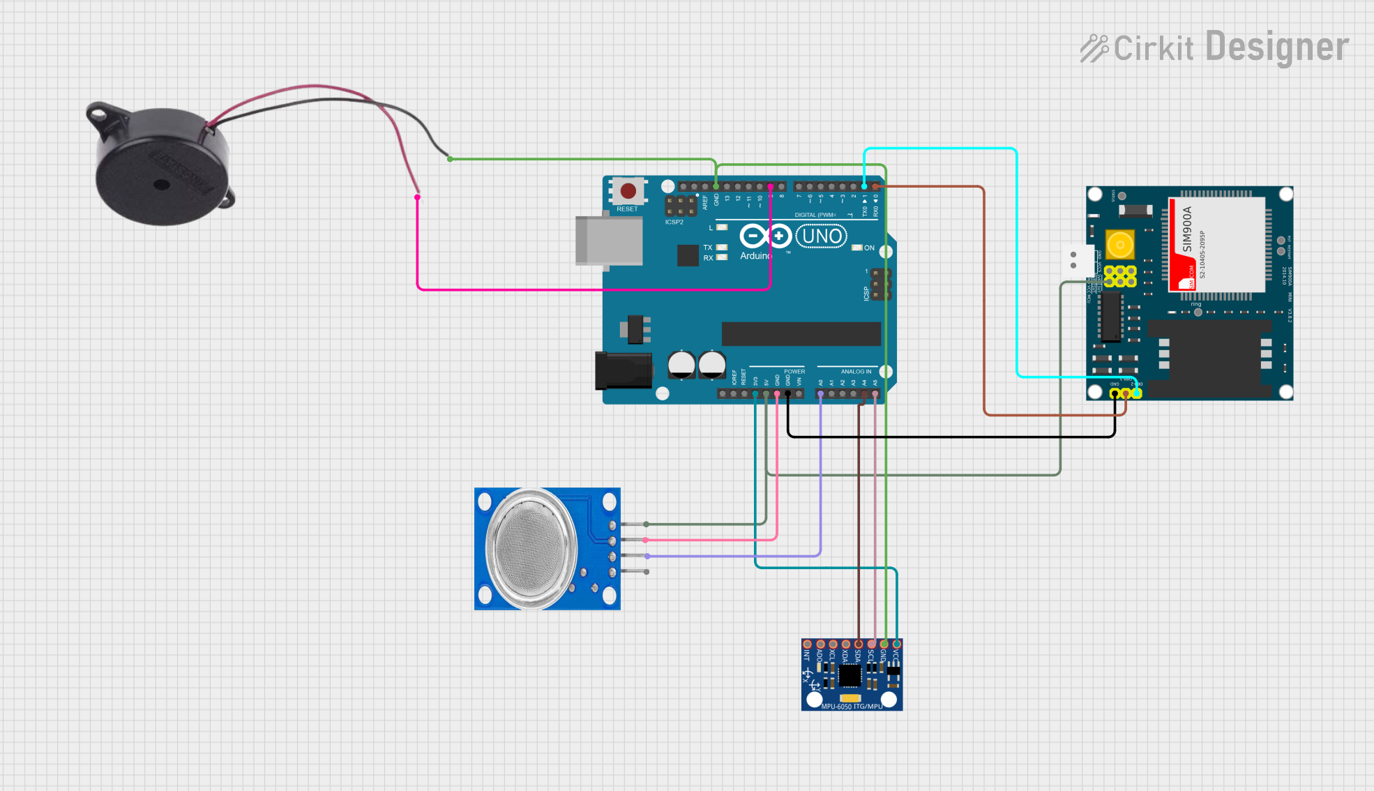
Explore Projects Built with GY-85
Technical Specifications
The GY-85 module is built around three key sensors:
- ADXL345: A 3-axis accelerometer for measuring acceleration.
- ITG-3200: A 3-axis gyroscope for angular velocity measurements.
- HMC5883L: A 3-axis magnetometer for detecting magnetic fields.
Key Technical Details
- Operating Voltage: 3.3V to 5V
- Communication Protocol: I²C (Inter-Integrated Circuit)
- I²C Address:
- ADXL345: 0x53
- ITG-3200: 0x68
- HMC5883L: 0x1E
- Power Consumption: Low power consumption for battery-powered applications
- Dimensions: Approximately 20mm x 20mm
- Temperature Range: -40°C to +85°C
Pin Configuration and Descriptions
The GY-85 module has 6 pins for interfacing. The table below describes each pin:
| Pin Name | Description |
|---|---|
| VCC | Power supply input (3.3V to 5V) |
| GND | Ground connection |
| SDA | I²C data line for communication |
| SCL | I²C clock line for communication |
| XDA | Auxiliary I²C data line (used for daisy-chaining multiple I²C devices) |
| XCL | Auxiliary I²C clock line (used for daisy-chaining multiple I²C devices) |
Usage Instructions
How to Use the GY-85 in a Circuit
- Power the Module: Connect the VCC pin to a 3.3V or 5V power source and the GND pin to ground.
- I²C Communication: Connect the SDA and SCL pins to the corresponding I²C pins on your microcontroller (e.g., Arduino UNO).
- Pull-Up Resistors: Ensure that the I²C lines (SDA and SCL) have pull-up resistors (typically 4.7kΩ) if not already present on the module.
- Addressing the Sensors: Use the I²C addresses of the individual sensors (ADXL345, ITG-3200, HMC5883L) to communicate with them.
Important Considerations and Best Practices
- Voltage Compatibility: Ensure your microcontroller's I²C pins are compatible with the GY-85's voltage levels (3.3V or 5V).
- Calibration: Calibrate the sensors for accurate readings, especially the magnetometer, which may require hard-iron and soft-iron calibration.
- Noise Filtering: Use software filters to reduce noise in the sensor readings.
- Mounting Orientation: Secure the module firmly to avoid vibrations that can affect sensor accuracy.
Example Code for Arduino UNO
Below is an example Arduino sketch to read data from the GY-85 module:
#include <Wire.h>

// I²C addresses for the sensors
#define ADXL345_ADDR 0x53  // Accelerometer
#define ITG3200_ADDR 0x68  // Gyroscope
#define HMC5883L_ADDR 0x1E // Magnetometer

void setup() {
  Wire.begin(); // Initialize I²C communication
  Serial.begin(9600); // Start serial communication for debugging

  // Initialize ADXL345 (Accelerometer)
  Wire.beginTransmission(ADXL345_ADDR);
  Wire.write(0x2D); // Power control register
  Wire.write(0x08); // Set measurement mode
  Wire.endTransmission();

  // Initialize ITG-3200 (Gyroscope)
  Wire.beginTransmission(ITG3200_ADDR);
  Wire.write(0x3E); // Power management register
  Wire.write(0x00); // Set normal mode
  Wire.endTransmission();

  // Initialize HMC5883L (Magnetometer)
  Wire.beginTransmission(HMC5883L_ADDR);
  Wire.write(0x00); // Configuration register A
  Wire.write(0x70); // Set 8-average, 15 Hz default
  Wire.endTransmission();
}

void loop() {
  // Read data from ADXL345 (Accelerometer)
  Wire.beginTransmission(ADXL345_ADDR);
  Wire.write(0x32); // Start reading from data registers
  Wire.endTransmission(false);
  Wire.requestFrom(ADXL345_ADDR, 6); // Request 6 bytes (X, Y, Z)
  int16_t ax = Wire.read() | (Wire.read() << 8);
  int16_t ay = Wire.read() | (Wire.read() << 8);
  int16_t az = Wire.read() | (Wire.read() << 8);

  // Print accelerometer data
  Serial.print("Accel X: "); Serial.print(ax);
  Serial.print(" Y: "); Serial.print(ay);
  Serial.print(" Z: "); Serial.println(az);

  delay(500); // Delay for readability
}
Troubleshooting and FAQs
Common Issues
No Data from Sensors:
- Cause: Incorrect I²C wiring or missing pull-up resistors.
- Solution: Verify the SDA and SCL connections and ensure pull-up resistors are in place.
Inaccurate Readings:
- Cause: Lack of calibration or external interference.
- Solution: Calibrate the sensors and minimize magnetic or vibrational interference.
Module Not Detected:
- Cause: Incorrect I²C address or power supply issues.
- Solution: Double-check the I²C addresses and ensure the module is powered correctly.
FAQs
Can the GY-85 work with 5V microcontrollers?
- Yes, the GY-85 is compatible with both 3.3V and 5V systems.
How do I calibrate the magnetometer?
- Use a calibration routine to account for hard-iron and soft-iron distortions. Libraries like
Adafruit_Sensorcan help.
- Use a calibration routine to account for hard-iron and soft-iron distortions. Libraries like
Can I use the GY-85 with other I²C devices?
- Yes, the GY-85 supports daisy-chaining via its auxiliary I²C lines (XDA and XCL).
By following this documentation, you can effectively integrate the GY-85 module into your projects for accurate motion and orientation sensing.