How to Use Adafruit 2.8inch Resistive TFT: Examples, Pinouts, and Specs
Introduction
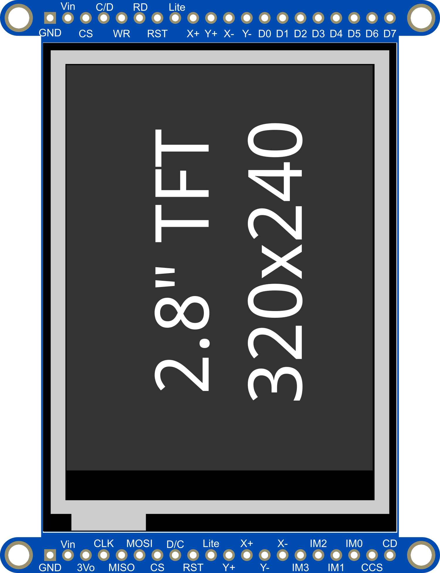
The Adafruit 2.8inch Resistive TFT is a versatile and vibrant touch screen display module that features a 2.8-inch color TFT LCD screen. With resistive touch capability, it offers a resolution of 320x240 pixels, enabling it to display detailed graphics and text. This module is widely compatible with various microcontrollers and single-board computers, such as the Arduino UNO, making it an excellent choice for embedded applications ranging from handheld devices to interactive control panels.
Explore Projects Built with Adafruit 2.8inch Resistive TFT

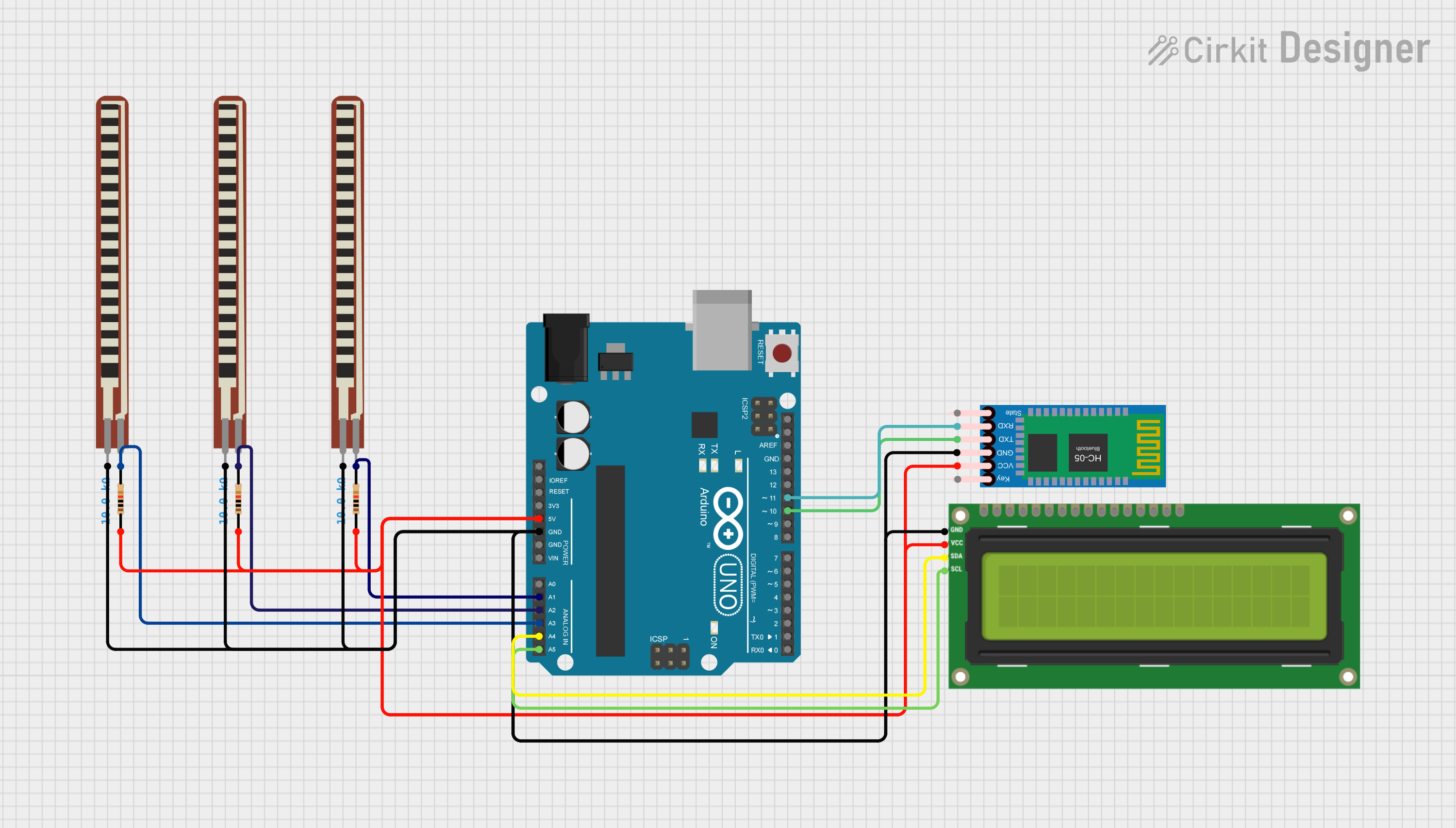
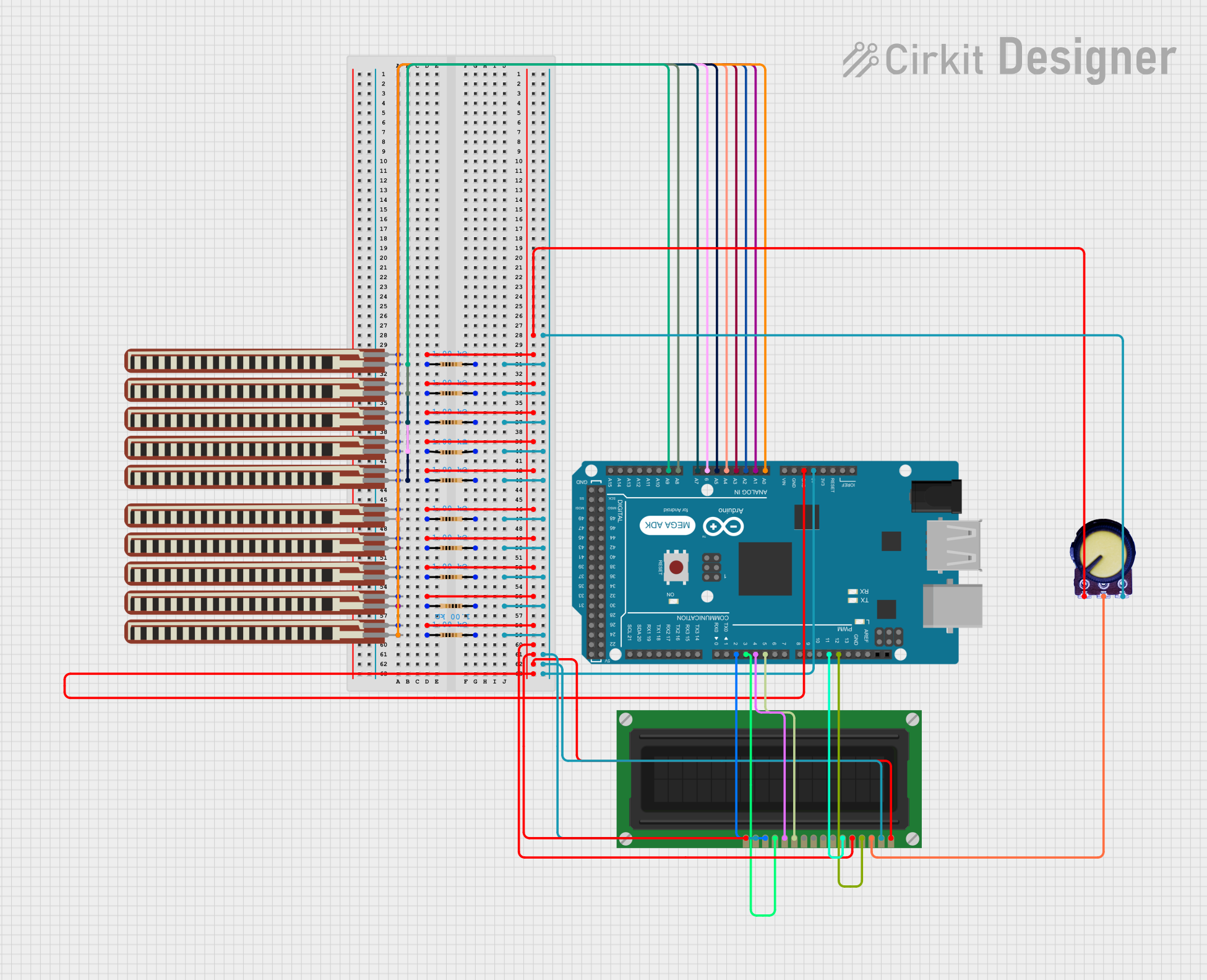
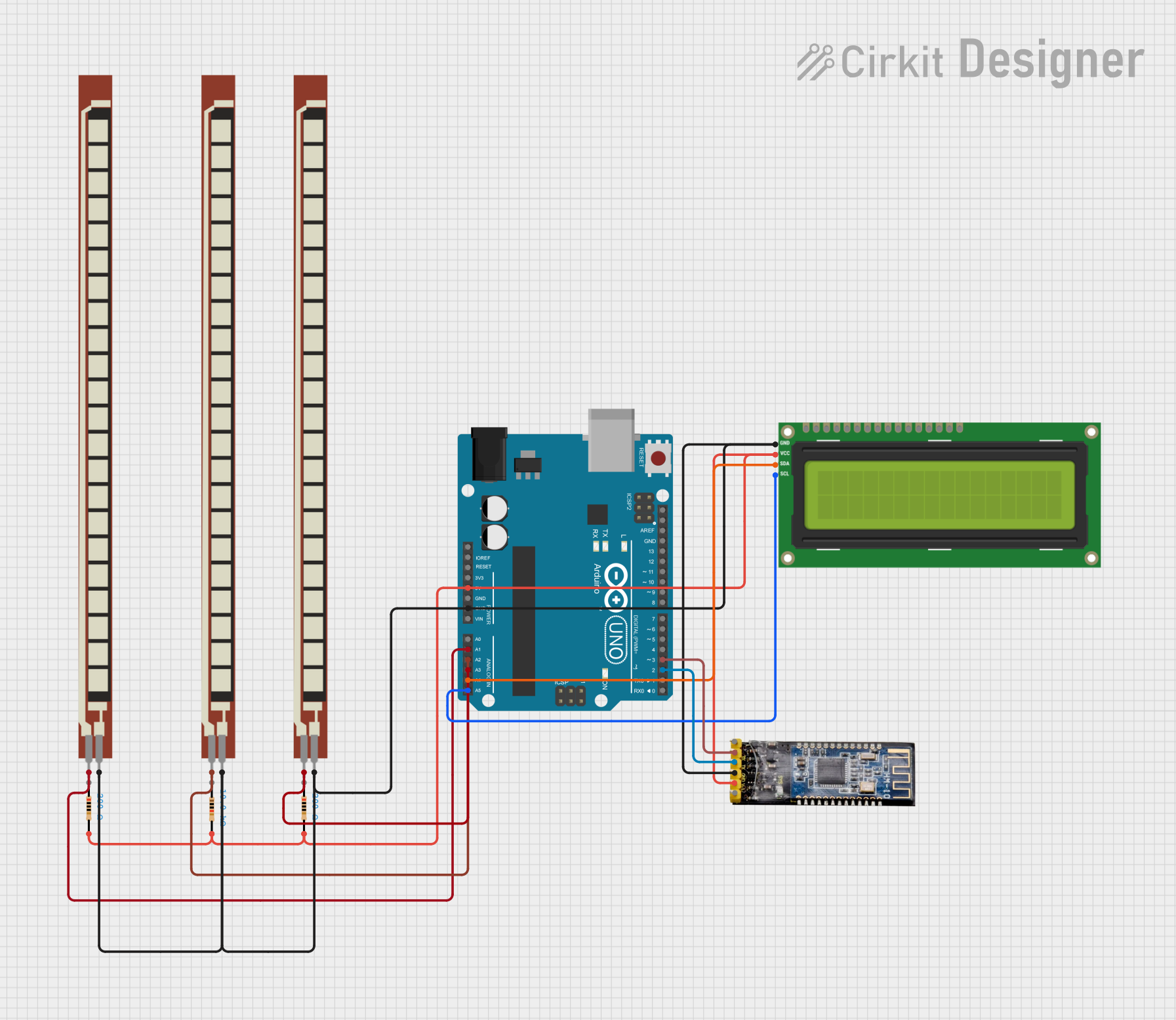
Explore Projects Built with Adafruit 2.8inch Resistive TFT
Common Applications and Use Cases
- DIY electronics projects
- Interactive control panels for devices
- Handheld instruments with graphical interfaces
- Educational tools and demonstrations
- Prototyping for user interfaces
Technical Specifications
Key Technical Details
- Display Size: 2.8 inches diagonal
- Resolution: 320x240 pixels
- Interface: SPI (Serial Peripheral Interface)
- Touch Screen: Resistive touch panel
- Operating Voltage: 3.3V to 5V
- Logic Level: 3.3V (5V tolerant)
Pin Configuration and Descriptions
| Pin Number | Pin Name | Description |
|---|---|---|
| 1 | VCC | Power supply (3.3V to 5V) |
| 2 | GND | Ground |
| 3 | CS | Chip Select for the TFT |
| 4 | RESET | Reset pin for the TFT |
| 5 | D/C | Data/Command control pin |
| 6 | MOSI | Master Out Slave In for SPI communication |
| 7 | SCK | Serial Clock for SPI communication |
| 8 | MISO | Master In Slave Out for SPI communication |
| 9 | T_CS | Chip Select for the touch screen |
| 10 | T_IRQ | Touch screen interrupt pin |
Usage Instructions
How to Use the Component in a Circuit
- Power Connections: Connect the VCC pin to a 3.3V or 5V power supply and the GND pin to the ground.
- SPI Connections: Connect the SCK, MOSI, and MISO pins to the corresponding SPI pins on your microcontroller.
- Control Pins: Connect the CS, RESET, and D/C pins to available digital pins on your microcontroller.
- Touch Screen Pins: Connect the T_CS pin to a digital pin for touch control and the T_IRQ pin if you wish to use the touch interrupt feature.
Important Considerations and Best Practices
- Use a level shifter if your microcontroller operates at a logic level higher than 3.3V.
- Ensure that the display is properly supported to prevent flexing and potential damage to the touch screen.
- Avoid applying excessive force to the touch screen to prevent damage.
- Keep the screen clean and free from dust and fingerprints for optimal touch sensitivity.
Example Code for Arduino UNO
#include <Adafruit_GFX.h>         // Core graphics library
#include <Adafruit_TFTLCD.h>      // Hardware-specific library

#define LCD_CS A3 // Chip Select goes to Analog 3
#define LCD_CD A2 // Command/Data goes to Analog 2
#define LCD_WR A1 // LCD Write goes to Analog 1
#define LCD_RD A0 // LCD Read goes to Analog 0
#define LCD_RESET A4 // Can alternately just connect to Arduino's reset pin

Adafruit_TFTLCD tft(LCD_CS, LCD_CD, LCD_WR, LCD_RD, LCD_RESET);

void setup() {
  tft.reset();
  uint16_t identifier = tft.readID();
  tft.begin(identifier);
  tft.fillScreen(BLACK);
  tft.setCursor(0, 0);
  tft.setTextColor(WHITE);
  tft.setTextSize(1);
  tft.println("Hello, World!");
}

void loop() {
  // Main loop - No code needed for static display
}
Ensure you have installed the Adafruit GFX and TFTLCD libraries before uploading this code to your Arduino UNO.
Troubleshooting and FAQs
Common Issues Users Might Face
- Display not powering on: Check the power connections and ensure the correct voltage is applied.
- No display output: Verify that the SPI connections are correct and that the correct pins are used for CS, RESET, and D/C.
- Touch not responsive: Ensure that the T_CS pin is connected properly and that the touch screen is calibrated.
Solutions and Tips for Troubleshooting
- Double-check wiring against the pin configuration table.
- Make sure that the libraries are correctly installed in the Arduino IDE.
- Use serial debugging to check for any error messages or codes.
- Calibrate the touch screen using the calibration sketch provided by Adafruit.
FAQs
Q: Can I use this display with a 5V microcontroller? A: Yes, the display is 5V tolerant, but it is recommended to use a level shifter for logic levels.
Q: How do I calibrate the touch screen? A: Adafruit provides a calibration sketch that can be used to calibrate the touch screen. Follow the instructions in the sketch comments.
Q: Can I display images on the screen?
A: Yes, the Adafruit GFX library supports bitmap images. You can use the drawBitmap function to display images stored in the microcontroller's memory.
For further assistance, consult the Adafruit forums or the community resources available for the Adafruit 2.8inch Resistive TFT.