How to Use MKS SERVO 57D: Examples, Pinouts, and Specs
Introduction
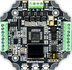
The MKS SERVO 57D (Manufacturer Part ID: MKS_SERVO57_CAN) is a high-performance digital servo motor designed by Makerbase. It is engineered for precision control in applications such as robotics, CNC machines, and RC vehicles. With its robust metal gear train, high torque output, and fast response times, the MKS SERVO 57D is ideal for demanding tasks requiring accuracy and reliability.
Explore Projects Built with MKS SERVO 57D
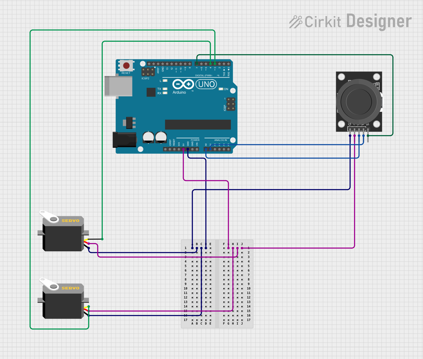
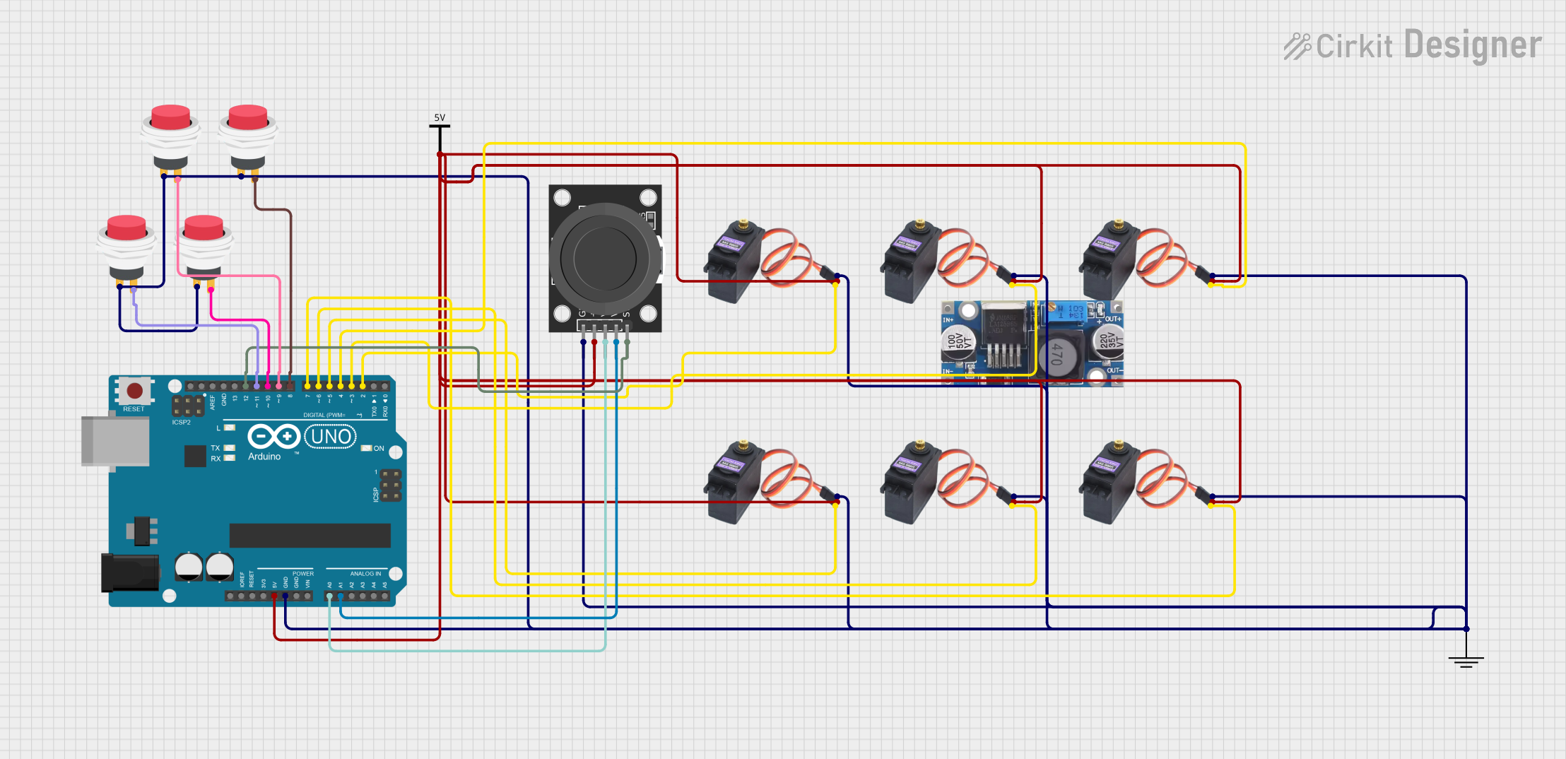
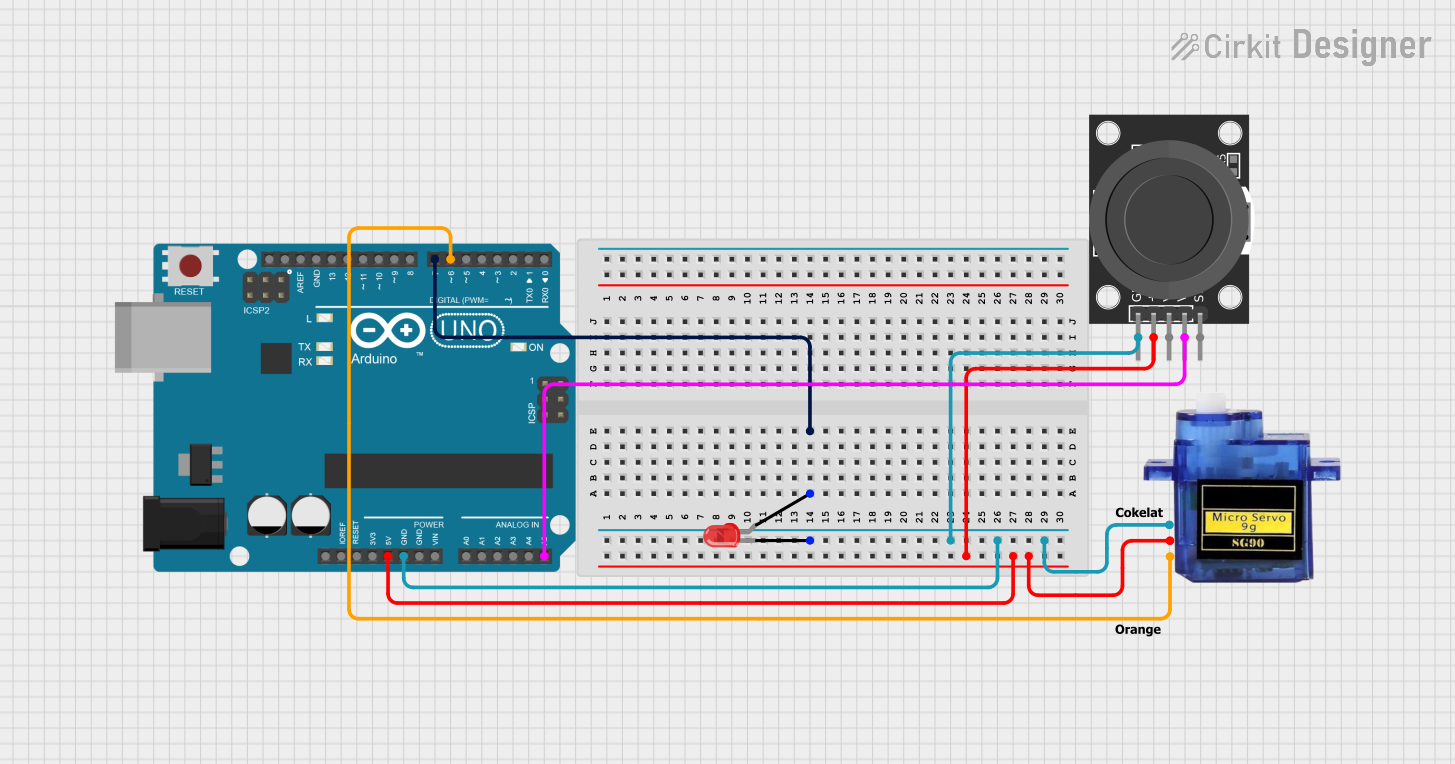
Explore Projects Built with MKS SERVO 57D
Common Applications
- Robotics (e.g., robotic arms, humanoid robots)
- CNC machines and 3D printers
- RC vehicles (cars, planes, and boats)
- Industrial automation systems
- Precision positioning systems
Technical Specifications
Key Technical Details
| Parameter | Value |
|---|---|
| Operating Voltage | 24V DC |
| Communication Protocol | CAN (Controller Area Network) |
| Torque Rating | 2.2 Nm |
| Maximum Speed | 3000 RPM |
| Gear Type | Metal Gear Train |
| Control Signal | CAN bus commands |
| Dimensions | 57mm x 57mm x 76mm |
| Weight | 650g |
| Operating Temperature | -20°C to 60°C |
Pin Configuration and Descriptions
The MKS SERVO 57D features a connector for power and communication. Below is the pinout for the servo's interface:
| Pin Number | Name | Description |
|---|---|---|
| 1 | V+ | Positive power supply (24V DC) |
| 2 | GND | Ground connection |
| 3 | CAN_H | CAN bus high signal |
| 4 | CAN_L | CAN bus low signal |
| 5 | Enable | Enable signal for activating the servo motor |
Usage Instructions
How to Use the MKS SERVO 57D in a Circuit
- Power Supply: Connect the servo's
V+andGNDpins to a 24V DC power source. Ensure the power supply can provide sufficient current for the servo's operation. - CAN Communication: Connect the
CAN_HandCAN_Lpins to a CAN bus network. Use a compatible CAN controller to send commands to the servo. - Enable Signal: Use the
Enablepin to activate the servo. This pin can be connected to a microcontroller or external switch. - Commanding the Servo: Send position, speed, or torque commands via the CAN bus protocol. Refer to the Makerbase CAN command set for detailed instructions.
Important Considerations and Best Practices
- Power Requirements: Ensure the power supply is stable and capable of delivering the required current to avoid performance issues.
- CAN Termination: Use a 120-ohm termination resistor at the end of the CAN bus to ensure proper communication.
- Mounting: Securely mount the servo to prevent vibrations or misalignment during operation.
- Heat Management: Avoid prolonged operation at maximum torque to prevent overheating. Ensure adequate ventilation around the servo.
Example: Connecting to an Arduino UNO
To use the MKS SERVO 57D with an Arduino UNO, you will need a CAN bus shield. Below is an example code snippet to send a position command to the servo:
#include <SPI.h>
#include <mcp_can.h>

// Define CAN bus pins for the shield
#define CAN_CS 10  // Chip Select pin for CAN shield
MCP_CAN CAN(CAN_CS);  // Create CAN object

void setup() {
  Serial.begin(115200);
  while (!Serial);

  // Initialize CAN bus at 500 kbps
  if (CAN.begin(MCP_ANY, 500000, MCP_8MHZ) == CAN_OK) {
    Serial.println("CAN bus initialized successfully!");
  } else {
    Serial.println("Error initializing CAN bus.");
    while (1);
  }
  CAN.setMode(MCP_NORMAL);  // Set CAN bus to normal mode
}

void loop() {
  // Example: Send a position command to the servo
  unsigned char data[8] = {0x01, 0x00, 0x00, 0x00, 0x00, 0x00, 0x00, 0x00};
  // 0x01 is the command ID for position control (example only)
  // Remaining bytes represent the position value (e.g., 0x00000000)

  if (CAN.sendMsgBuf(0x100, 0, 8, data) == CAN_OK) {
    Serial.println("Position command sent successfully!");
  } else {
    Serial.println("Error sending position command.");
  }

  delay(1000);  // Wait 1 second before sending the next command
}
Note: Replace the data array with the appropriate command and position values based on the Makerbase CAN protocol documentation.
Troubleshooting and FAQs
Common Issues and Solutions
Servo Not Responding:
- Cause: Incorrect wiring or power supply issues.
- Solution: Double-check all connections and ensure the power supply meets the servo's requirements.
CAN Communication Fails:
- Cause: Missing or incorrect termination resistor.
- Solution: Add a 120-ohm resistor at the end of the CAN bus.
Overheating:
- Cause: Prolonged operation at maximum torque or poor ventilation.
- Solution: Reduce the load on the servo and ensure proper airflow around the device.
Erratic Movement:
- Cause: Electrical noise or unstable power supply.
- Solution: Use decoupling capacitors and ensure the power supply is stable.
FAQs
Q: Can the MKS SERVO 57D operate at 12V?
A: No, the servo requires a 24V DC power supply for proper operation.
Q: What is the maximum cable length for the CAN bus?
A: The maximum cable length depends on the baud rate. For 500 kbps, the recommended maximum length is approximately 100 meters.
Q: Is the servo compatible with other microcontrollers?
A: Yes, the servo can be controlled by any microcontroller with CAN bus support, such as Arduino, Raspberry Pi, or STM32.
Q: Does the servo support feedback?
A: Yes, the servo provides position and status feedback via the CAN bus protocol. Refer to the Makerbase documentation for details.