
How to Use Arduino Power Driver Shield: Examples, Pinouts, and Specs
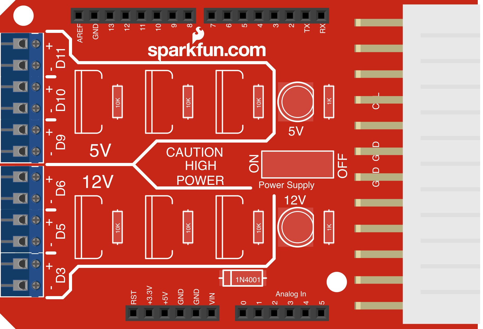
 Design with Arduino Power Driver Shield in Cirkit Designer
Introduction
The Arduino Power Driver Shield (Manufacturer Part ID: DEV-10618) by SparkFun is a versatile shield designed to enhance the power-handling capabilities of Arduino boards. It allows users to control high-current devices such as motors, solenoids, and high-power LEDs while protecting the Arduino from overload and damage. This shield is ideal for projects requiring robust power management and control of high-current loads.
Explore Projects Built with Arduino Power Driver Shield
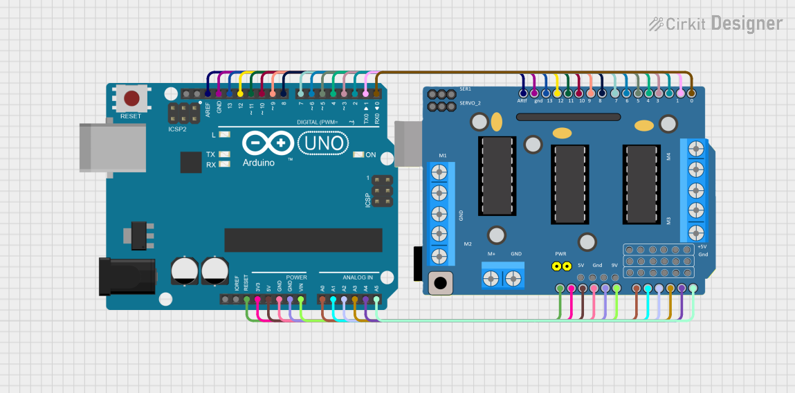 Open Project in Cirkit Designer
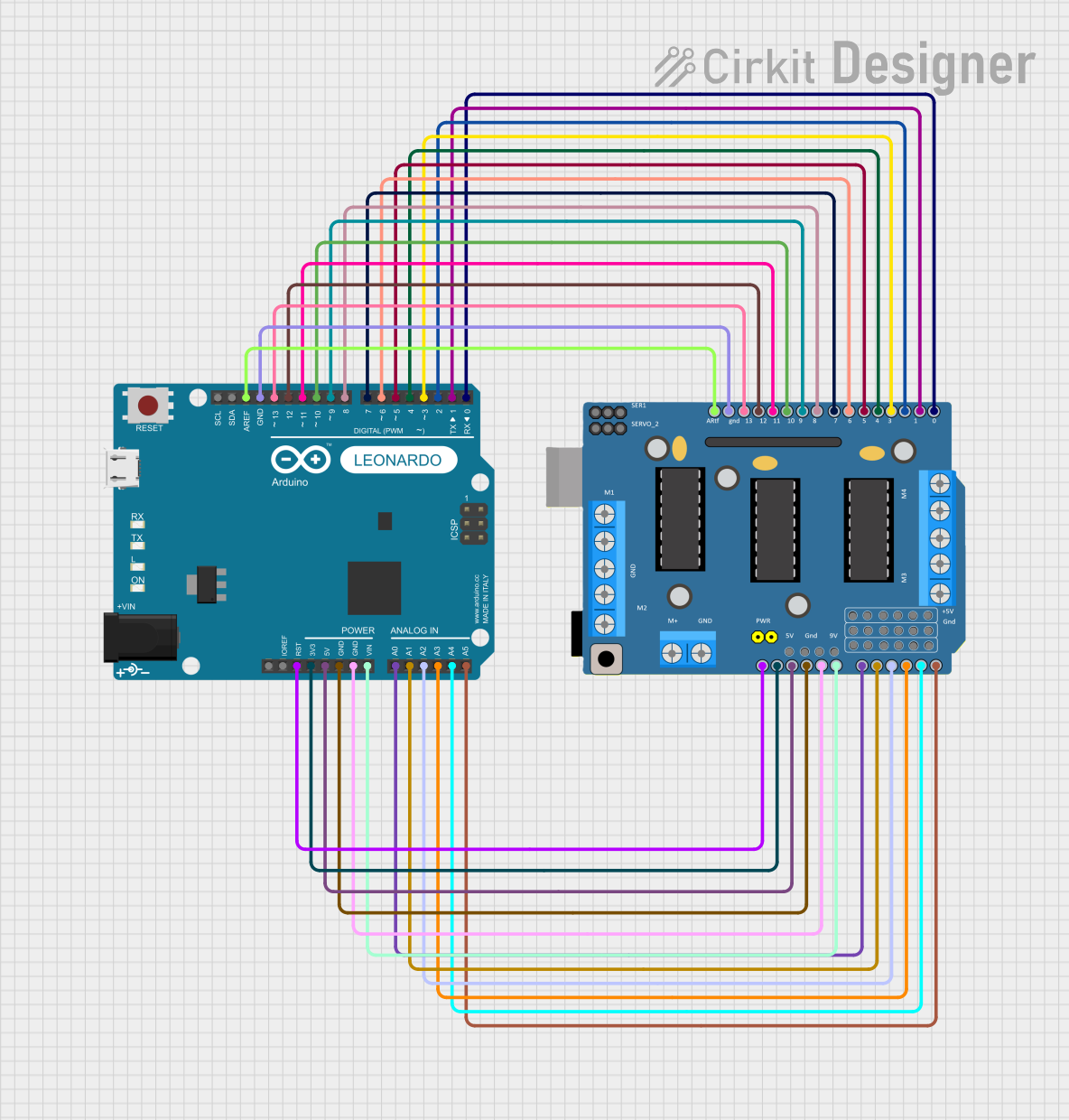 Open Project in Cirkit Designer
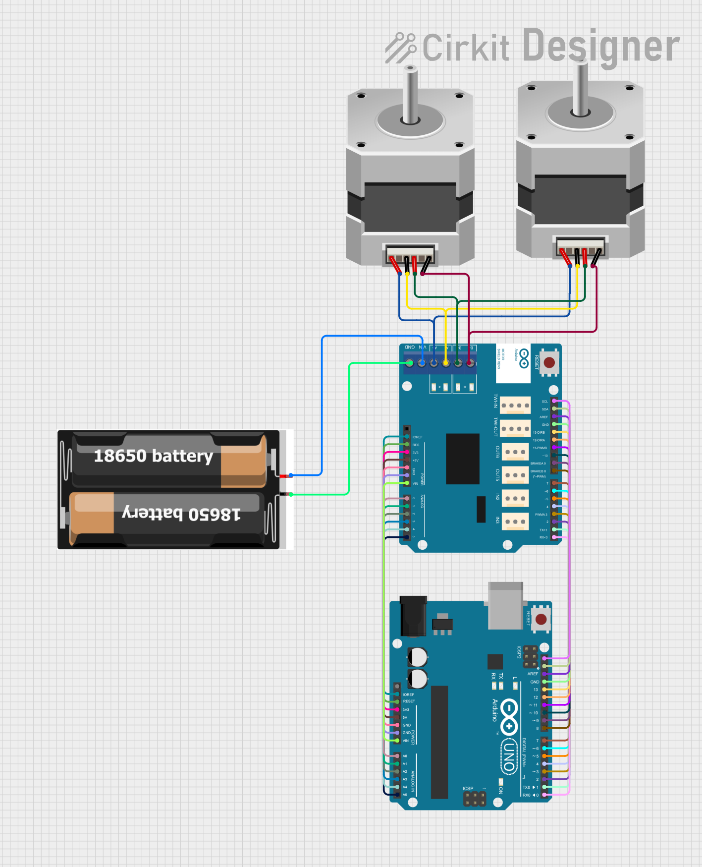 Open Project in Cirkit Designer
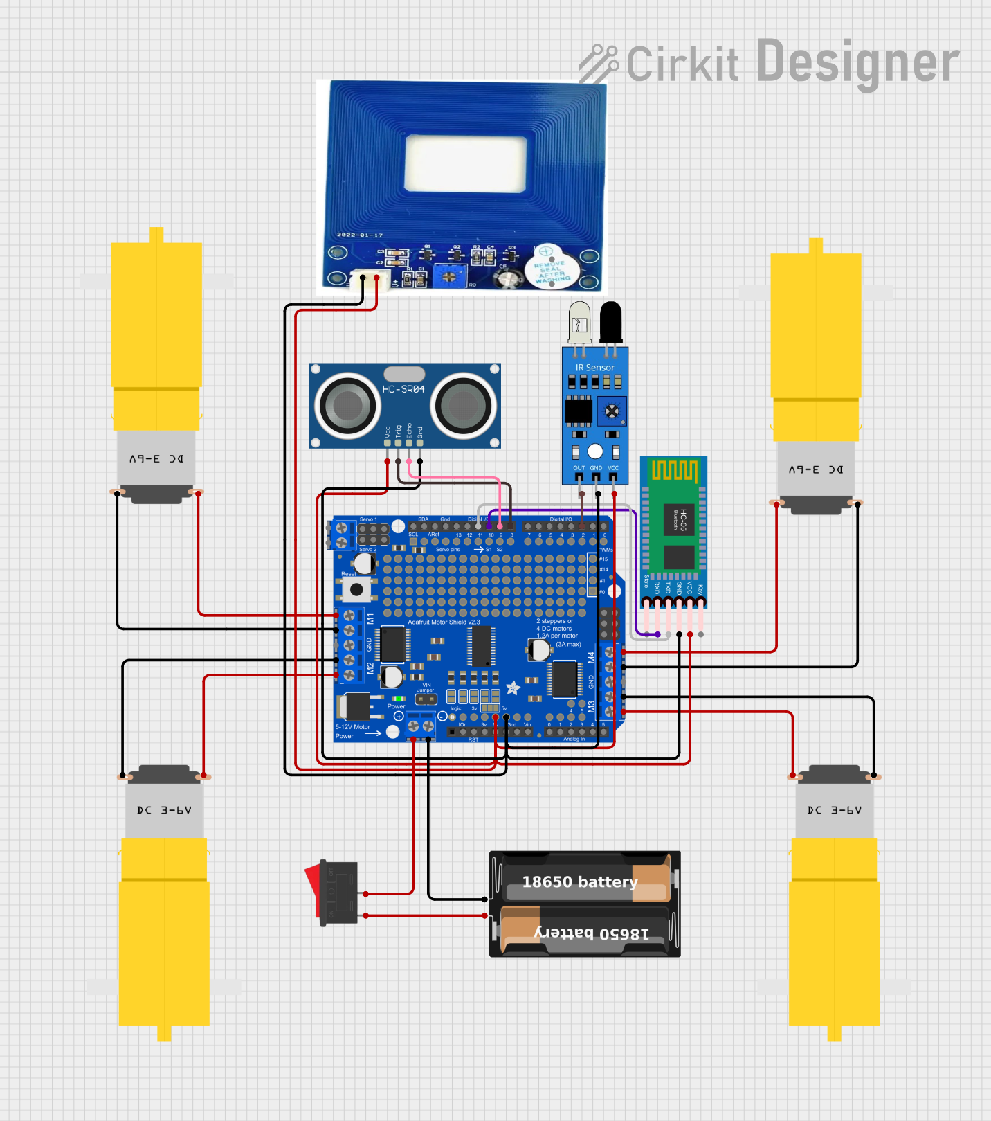 Open Project in Cirkit Designer
Explore Projects Built with Arduino Power Driver Shield
Open Project in Cirkit DesignerOpen Project in Cirkit DesignerOpen Project in Cirkit DesignerOpen Project in Cirkit DesignerCommon Applications
- Driving DC motors and stepper motors
- Controlling solenoids and relays
- Powering high-current LEDs or LED strips
- Robotics and automation systems
- Home automation and IoT projects
Technical Specifications
The following table outlines the key technical details of the Arduino Power Driver Shield:
| Specification | Details |
|---|---|
| Input Voltage | 6V to 15V (external power supply required for high-current loads) |
| Output Current | Up to 2A per channel (4 channels total) |
| Channels | 4 independent high-current channels |
| Control Logic Voltage | 5V (compatible with standard Arduino logic levels) |
| Protection Features | Overcurrent protection, thermal shutdown, and flyback diode protection |
| Dimensions | 68.6mm x 53.3mm (fits standard Arduino form factor) |
| Weight | Approximately 30g |
Pin Configuration and Descriptions
The Arduino Power Driver Shield has a straightforward pin layout. The table below describes the key pins and their functions:
| Pin | Description |
|---|---|
| VIN | External power input for high-current devices (6V to 15V). |
| GND | Ground connection shared between the shield and the Arduino. |
| IN1 - IN4 | Control inputs for channels 1 to 4. Connect to Arduino digital output pins. |
| OUT1 - OUT4 | High-current outputs for channels 1 to 4. Connect to the load (e.g., motor). |
| EN | Enable pin for the shield. Pull HIGH to enable all channels. |
Usage Instructions
How to Use the Shield in a Circuit
- Mount the Shield: Place the Arduino Power Driver Shield on top of your Arduino board, ensuring the pins align correctly.
- Connect External Power: Connect a suitable external power supply (6V to 15V) to the VIN and GND terminals of the shield.
- Connect the Load: Attach the high-current devices (e.g., motors, LEDs) to the OUT1-OUT4 terminals.
- Control Signals: Use the Arduino's digital output pins to send control signals to IN1-IN4. These signals determine the state of each channel.
- Enable the Shield: Pull the EN pin HIGH to activate the shield. This can be done by connecting it to a 5V pin on the Arduino.
Important Considerations and Best Practices
- Power Supply: Ensure the external power supply can handle the total current required by all connected loads.
- Heat Dissipation: The shield may heat up during operation. Use proper ventilation or a heatsink if necessary.
- Flyback Protection: The shield includes built-in flyback diodes to protect against voltage spikes from inductive loads.
- Avoid Overloading: Do not exceed the 2A per channel limit to prevent damage to the shield.
Example Code for Arduino UNO
Below is an example code snippet to control a motor connected to channel 1 of the shield:
// Example: Controlling a motor using the Arduino Power Driver Shield
// Connect IN1 to Arduino pin 9, and EN to Arduino pin 8

#define EN_PIN 8    // Enable pin for the shield
#define IN1_PIN 9   // Control pin for channel 1

void setup() {
  pinMode(EN_PIN, OUTPUT);  // Set EN pin as output
  pinMode(IN1_PIN, OUTPUT); // Set IN1 pin as output

  digitalWrite(EN_PIN, HIGH); // Enable the shield
}

void loop() {
  digitalWrite(IN1_PIN, HIGH); // Turn on the motor
  delay(2000);                 // Run for 2 seconds

  digitalWrite(IN1_PIN, LOW);  // Turn off the motor
  delay(2000);                 // Wait for 2 seconds
}
Troubleshooting and FAQs
Common Issues and Solutions
Shield Not Powering On
- Cause: The EN pin is not pulled HIGH.
- Solution: Ensure the EN pin is connected to a 5V pin or set HIGH in your Arduino code.
Load Not Responding
- Cause: Incorrect wiring or insufficient power supply.
- Solution: Double-check all connections and ensure the external power supply meets the load's requirements.
Overheating
- Cause: Exceeding the 2A per channel limit or poor ventilation.
- Solution: Reduce the load current or improve ventilation around the shield.
Arduino Resetting
- Cause: Voltage spikes from inductive loads.
- Solution: Ensure proper flyback diode protection is in place (the shield includes this feature).
FAQs
Q: Can I use this shield with a 3.3V logic Arduino board?
A: No, the shield is designed for 5V logic levels and may not work reliably with 3.3V boards.
Q: What happens if I exceed the 2A per channel limit?
A: The shield's overcurrent protection will activate, shutting down the affected channel to prevent damage.
Q: Can I control all four channels simultaneously?
A: Yes, you can control all four channels independently or simultaneously, as long as the total current does not exceed the power supply's capacity.
Q: Is the shield compatible with all Arduino boards?
A: The shield is compatible with Arduino boards that follow the standard form factor, such as the Arduino UNO, Mega, and Leonardo.