
How to Use PLC OUTSEAL V3: Examples, Pinouts, and Specs
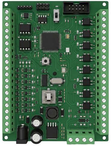
 Design with PLC OUTSEAL V3 in Cirkit Designer
Introduction
The PLC OUTSEAL V3 is a high-performance programmable logic controller (PLC) designed by OUTSEAL for industrial automation applications. This controller is engineered to operate reliably in harsh environments, thanks to its robust sealing that provides protection against dust and moisture. It supports a wide range of input/output (I/O) configurations, making it suitable for diverse automation tasks, from simple machine control to complex process management.
Explore Projects Built with PLC OUTSEAL V3
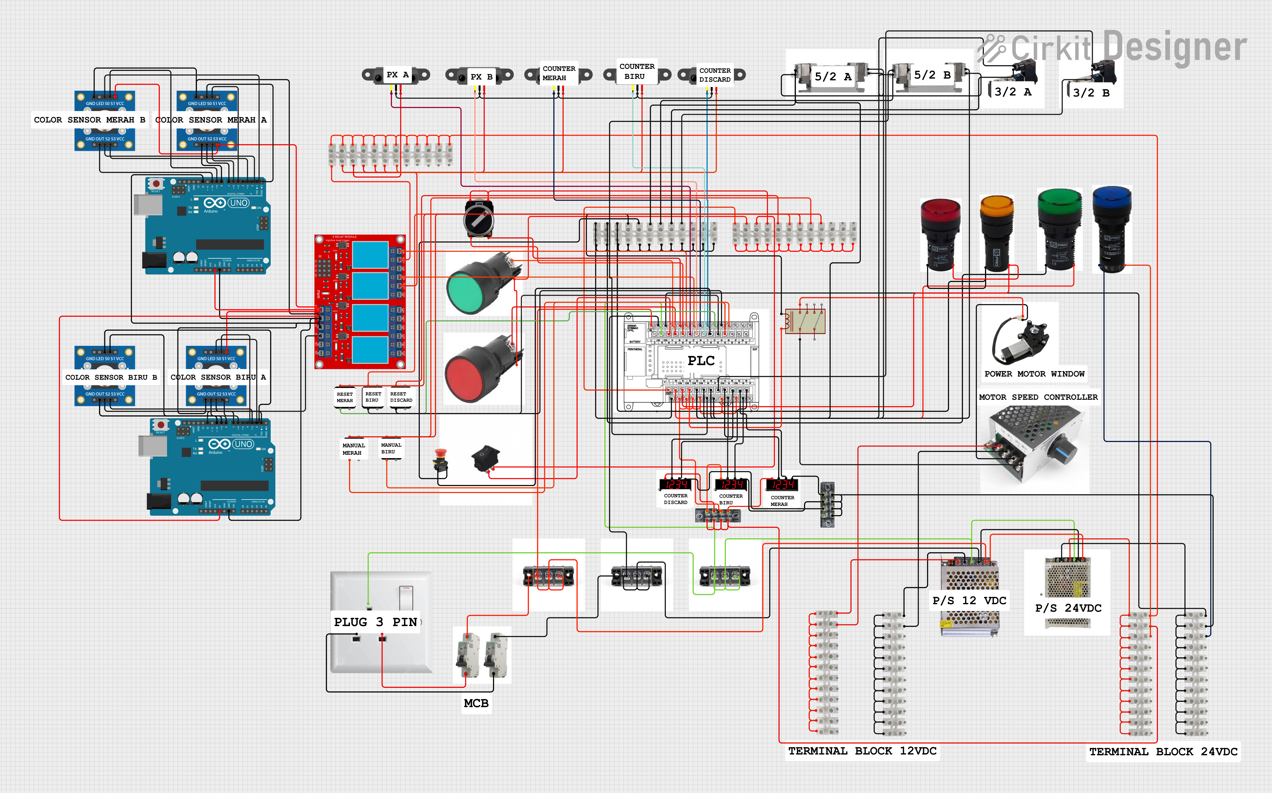 Open Project in Cirkit Designer
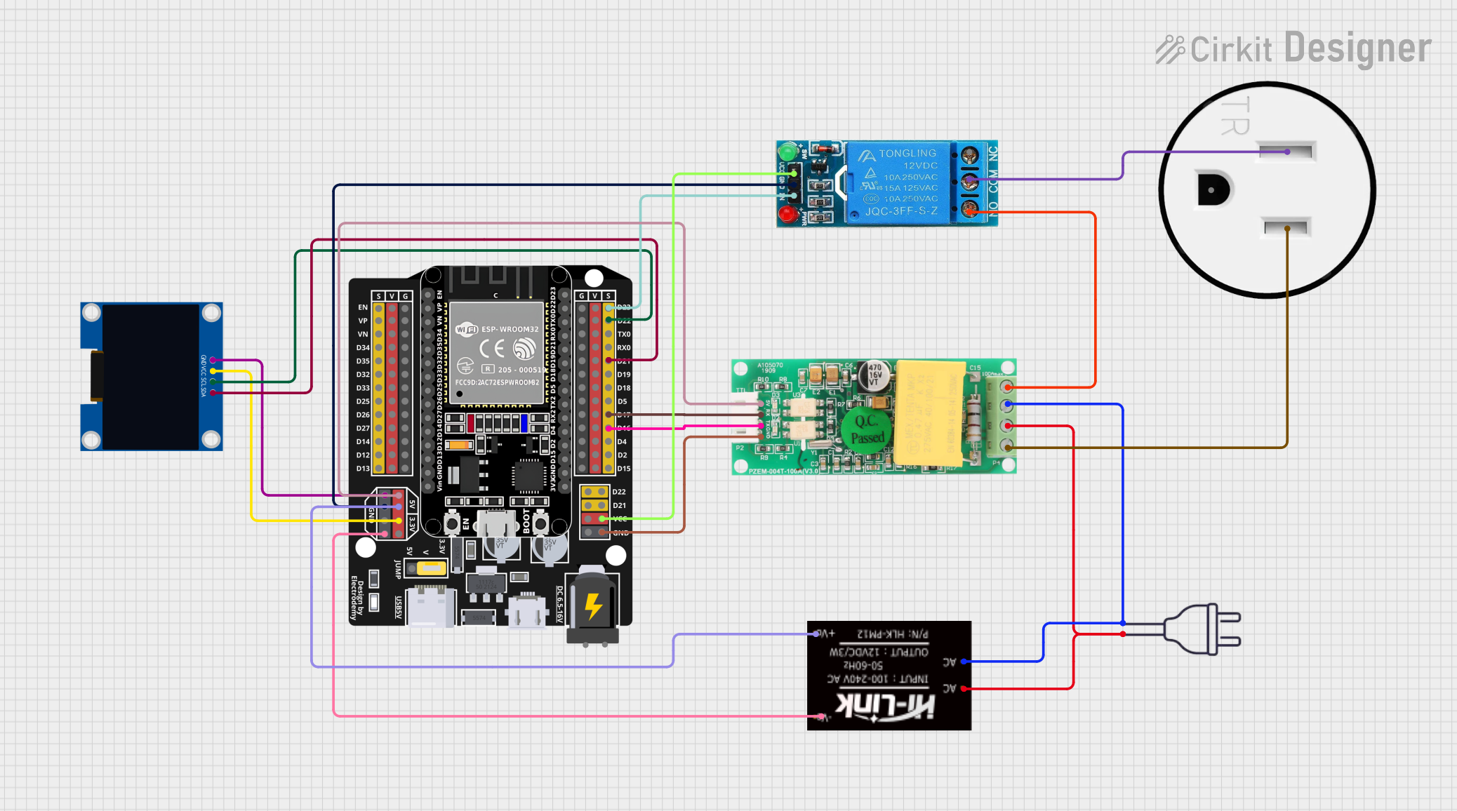 Open Project in Cirkit Designer
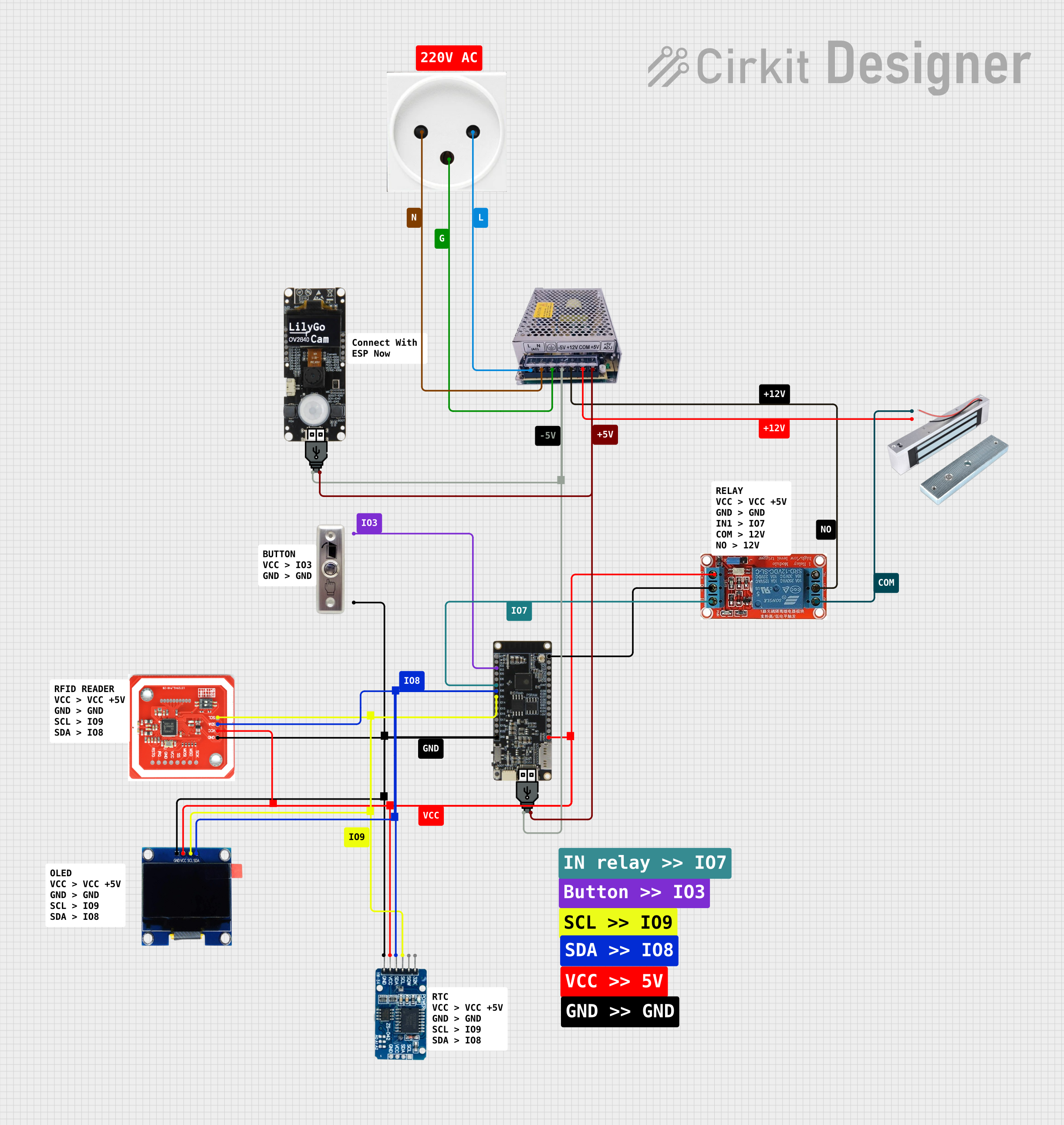 Open Project in Cirkit Designer
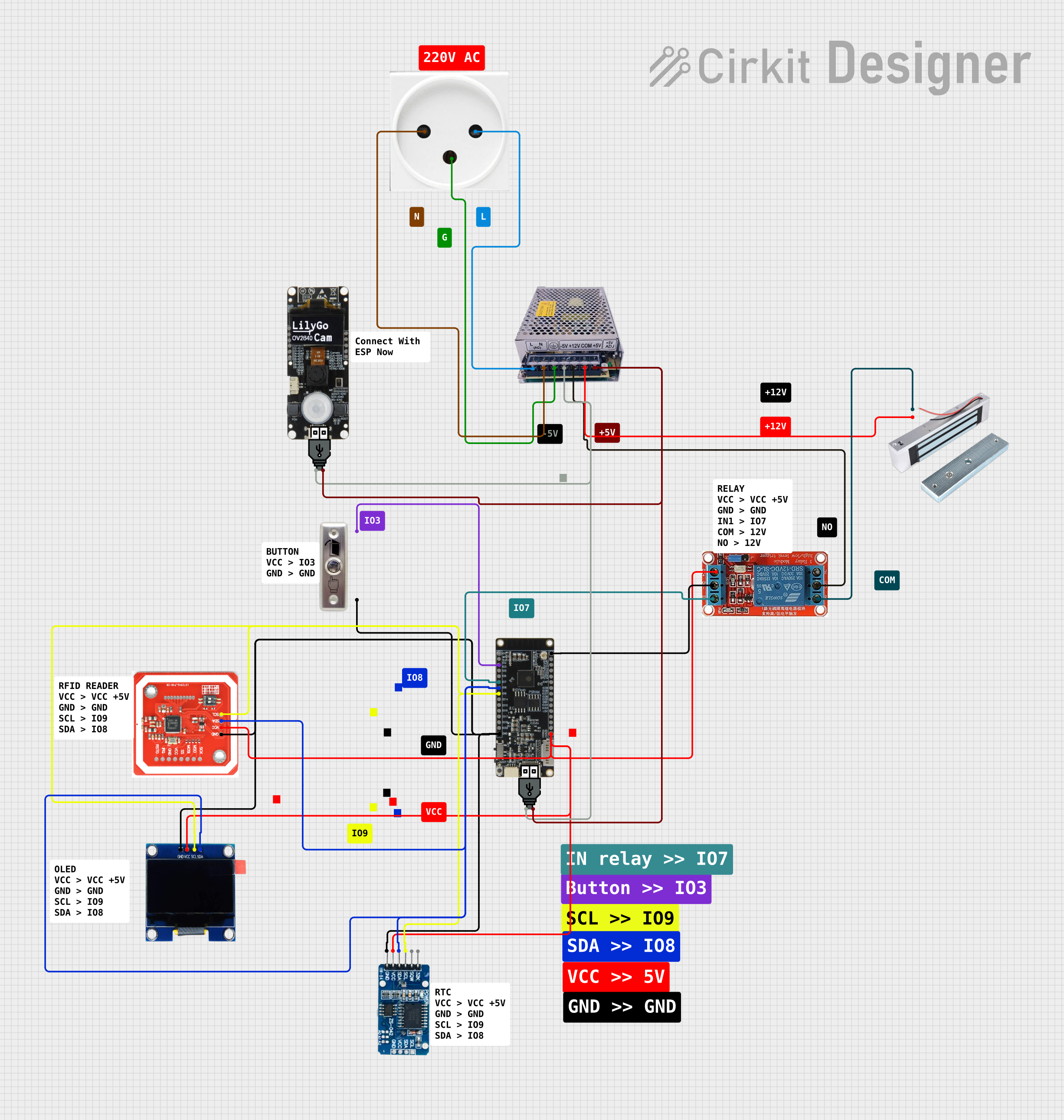 Open Project in Cirkit Designer
Explore Projects Built with PLC OUTSEAL V3
Open Project in Cirkit DesignerOpen Project in Cirkit DesignerOpen Project in Cirkit DesignerOpen Project in Cirkit DesignerCommon Applications and Use Cases
- Industrial machinery control
- Process automation in manufacturing plants
- Building automation systems
- Monitoring and control in harsh environments (e.g., factories, outdoor installations)
- Integration with sensors, actuators, and other industrial devices
Technical Specifications
Key Technical Details
| Parameter | Specification |
|---|---|
| Manufacturer | OUTSEAL |
| Part ID | PLC OUTSEAL V3 |
| Operating Voltage | 24V DC |
| Power Consumption | 10W (typical) |
| Input Channels | 8 digital inputs, 4 analog inputs |
| Output Channels | 8 digital outputs, 2 analog outputs |
| Communication Protocols | Modbus RTU, RS-485, Ethernet |
| Operating Temperature | -20°C to 60°C |
| Protection Rating | IP67 (dustproof and waterproof) |
| Programming Language | Ladder Logic, Function Block Diagram |
| Memory | 256 KB program memory, 512 KB data memory |
| Dimensions | 120mm x 80mm x 50mm |
Pin Configuration and Descriptions
Digital Input Pins
| Pin Number | Label | Description |
|---|---|---|
| DI1 | Digital In 1 | First digital input channel |
| DI2 | Digital In 2 | Second digital input channel |
| DI3 | Digital In 3 | Third digital input channel |
| DI4 | Digital In 4 | Fourth digital input channel |
| DI5 | Digital In 5 | Fifth digital input channel |
| DI6 | Digital In 6 | Sixth digital input channel |
| DI7 | Digital In 7 | Seventh digital input channel |
| DI8 | Digital In 8 | Eighth digital input channel |
Digital Output Pins
| Pin Number | Label | Description |
|---|---|---|
| DO1 | Digital Out 1 | First digital output channel |
| DO2 | Digital Out 2 | Second digital output channel |
| DO3 | Digital Out 3 | Third digital output channel |
| DO4 | Digital Out 4 | Fourth digital output channel |
| DO5 | Digital Out 5 | Fifth digital output channel |
| DO6 | Digital Out 6 | Sixth digital output channel |
| DO7 | Digital Out 7 | Seventh digital output channel |
| DO8 | Digital Out 8 | Eighth digital output channel |
Analog Input/Output Pins
| Pin Number | Label | Description |
|---|---|---|
| AI1 | Analog In 1 | First analog input channel |
| AI2 | Analog In 2 | Second analog input channel |
| AI3 | Analog In 3 | Third analog input channel |
| AI4 | Analog In 4 | Fourth analog input channel |
| AO1 | Analog Out 1 | First analog output channel |
| AO2 | Analog Out 2 | Second analog output channel |
Power and Communication Pins
| Pin Number | Label | Description |
|---|---|---|
| V+ | Power + | Positive power supply (24V DC) |
| V- | Power - | Negative power supply (ground) |
| COM1 | RS-485 A | RS-485 communication line A |
| COM2 | RS-485 B | RS-485 communication line B |
| ETH | Ethernet | Ethernet communication port |
Usage Instructions
How to Use the PLC OUTSEAL V3 in a Circuit
- Power Connection: Connect the V+ and V- pins to a 24V DC power supply. Ensure the power supply is stable and within the specified voltage range.
- Input Connections: Connect sensors or switches to the digital and analog input pins (DI1-DI8, AI1-AI4). Ensure the input signals are within the supported voltage/current range.
- Output Connections: Connect actuators, relays, or other devices to the digital and analog output pins (DO1-DO8, AO1-AO2). Verify that the connected devices do not exceed the output current rating.
- Communication Setup: Use the RS-485 or Ethernet ports to connect the PLC to a network or other devices. Configure the communication protocol (e.g., Modbus RTU) as needed.
- Programming: Use the OUTSEAL programming software to write and upload control logic to the PLC. Supported languages include Ladder Logic and Function Block Diagram.
- Testing: After programming, test the PLC in a controlled environment to ensure proper operation before deploying it in the field.
Important Considerations and Best Practices
- Ensure all connections are secure and properly insulated to prevent short circuits or damage.
- Use shielded cables for communication lines to minimize electromagnetic interference (EMI).
- Regularly inspect the PLC for signs of wear or damage, especially in harsh environments.
- Follow the manufacturer's guidelines for firmware updates and maintenance.
Example Code for Arduino UNO Integration
The PLC OUTSEAL V3 can communicate with an Arduino UNO via Modbus RTU over RS-485. Below is an example Arduino sketch for reading a digital input from the PLC:
#include <ModbusMaster.h>

// Instantiate ModbusMaster object
ModbusMaster node;

void setup() {
  Serial.begin(9600); // Initialize serial communication
  node.begin(1, Serial); // Set Modbus slave ID to 1
}

void loop() {
  uint8_t result;
  uint16_t data;

  // Read digital input status from PLC (address 0x0000)
  result = node.readDiscreteInputs(0x0000, 1);

  if (result == node.ku8MBSuccess) {
    data = node.getResponseBuffer(0); // Get the input status
    Serial.print("Digital Input 1 Status: ");
    Serial.println(data ? "ON" : "OFF");
  } else {
    Serial.println("Failed to read from PLC");
  }

  delay(1000); // Wait 1 second before next read
}
Troubleshooting and FAQs
Common Issues and Solutions
PLC Not Powering On
- Cause: Incorrect power supply connection or insufficient voltage.
- Solution: Verify the power supply voltage is 24V DC and check the V+ and V- connections.
Inputs/Outputs Not Responding
- Cause: Faulty wiring or incorrect configuration.
- Solution: Double-check all connections and ensure the PLC is programmed correctly.
Communication Failure
- Cause: Incorrect protocol settings or damaged cables.
- Solution: Verify the communication protocol (e.g., Modbus RTU) and inspect the cables for damage.
Moisture/Dust Ingress
- Cause: Damaged sealing or improper installation.
- Solution: Inspect the PLC's enclosure and ensure it is properly sealed. Replace damaged seals if necessary.
FAQs
Q: Can the PLC OUTSEAL V3 be used outdoors?
- A: Yes, its IP67 rating ensures protection against dust and water, making it suitable for outdoor use.
Q: What programming software is compatible with this PLC?
- A: The PLC OUTSEAL V3 is compatible with OUTSEAL's proprietary programming software.
Q: How do I update the firmware?
- A: Use the OUTSEAL programming software to check for updates and follow the on-screen instructions to update the firmware.
Q: Can I expand the I/O channels?
- A: Yes, the PLC supports expansion modules for additional I/O channels. Refer to the manufacturer's documentation for compatible modules.