Cirkit Designer Logo
Cirkit Designer
Your all-in-one circuit design IDE
Home / 
Component Documentation

How to Use PWM DC Motor Speed Control 5-16V - 10A: Examples, Pinouts, and Specs

Image of PWM DC Motor Speed Control 5-16V - 10A
Cirkit Designer LogoDesign with PWM DC Motor Speed Control 5-16V - 10A in Cirkit Designer

Introduction

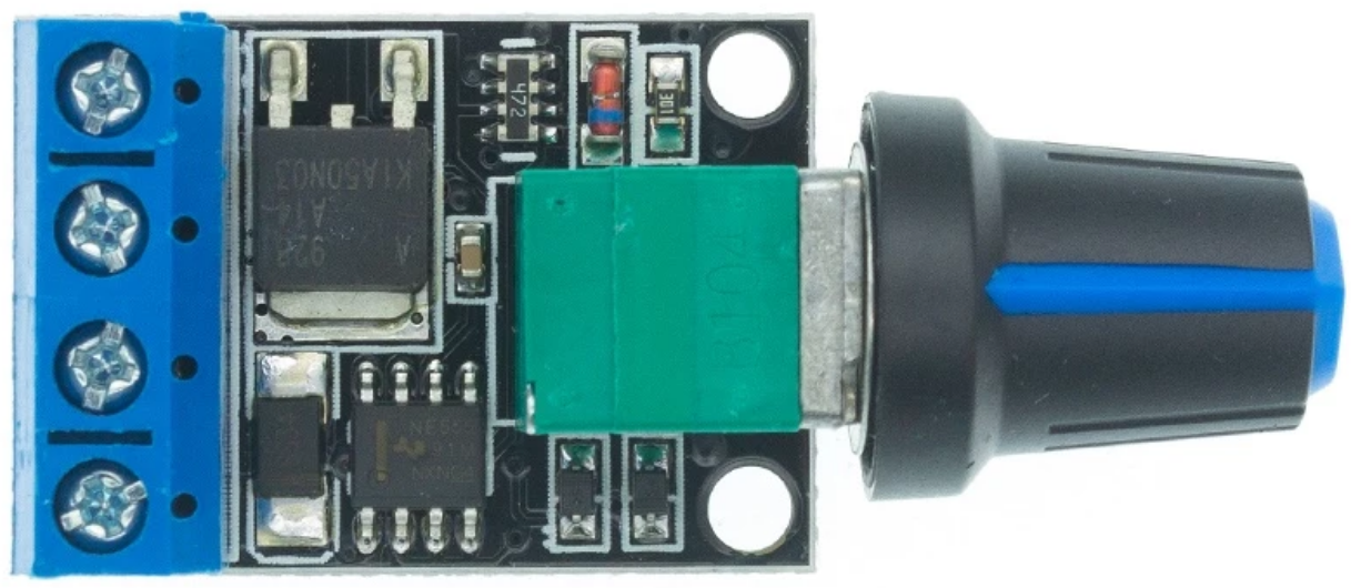
The PWM DC Motor Speed Control 5-16V - 10A is a versatile and efficient controller designed to regulate the speed of DC motors using Pulse Width Modulation (PWM) technology. This component allows precise control of motor speed by adjusting the duty cycle of the PWM signal, making it ideal for applications requiring variable motor speeds.

Explore Projects Built with PWM DC Motor Speed Control 5-16V - 10A

Use Cirkit Designer to design, explore, and prototype these projects online. Some projects support real-time simulation. Click "Open Project" to start designing instantly!
12V PWM-Controlled Water Pump System
Image of moter speed controller: A project utilizing PWM DC Motor Speed Control 5-16V - 10A in a practical application
This circuit is designed to control the speed of a water pump using a PWM DC motor speed controller. The 12V5Ah battery provides power to the speed controller, which in turn regulates the power supplied to the water pump, allowing for adjustable flow rates. There is no microcontroller code provided, indicating that the speed control is likely adjusted manually via the PWM controller.
Cirkit Designer LogoOpen Project in Cirkit Designer
PWM-Controlled DC Motor Speed Regulator with DC Barrel Jack Power Input
Image of Siren: A project utilizing PWM DC Motor Speed Control 5-16V - 10A in a practical application
This circuit controls the speed of a DC motor using a 12V PWM speed controller. Power is supplied to the speed controller through a 2.1mm DC barrel jack, which then modulates the voltage and current to the motor's terminals to adjust its speed. There is no microcontroller code involved, indicating that the speed control is likely adjusted manually via the speed controller's onboard settings.
Cirkit Designer LogoOpen Project in Cirkit Designer
Arduino Mega 2560 Controlled 250W DC Motor with BTS7960 Driver and Temperature-Based PWM
Image of DCmot+dst7960: A project utilizing PWM DC Motor Speed Control 5-16V - 10A in a practical application
This circuit is a motor control system that uses an Arduino Mega 2560 to regulate the speed of a 250W 12V DC motor via a BTS7960 motor driver. The Arduino reads temperature data from a sensor and adjusts the motor's PWM duty cycle accordingly, with power supplied by a 12V 5A power supply and controlled through a rocker switch.
Cirkit Designer LogoOpen Project in Cirkit Designer
Dual DC Motor Control Circuit with Speed Regulation and Indicator Lamp
Image of egg peeling machine: A project utilizing PWM DC Motor Speed Control 5-16V - 10A in a practical application
This circuit includes a 12V 200Ah battery that powers a water pump and two DC motors, each controlled by a separate 12v~40v 10A PWM DC motor speed controller. A rocker switch (SPST) is used to control the power flow to the water pump and a pilot lamp indicates when the pump is powered. The DC motors' speed can be adjusted by the PWM controllers, and wire connectors are used to organize the connections between components.
Cirkit Designer LogoOpen Project in Cirkit Designer

Explore Projects Built with PWM DC Motor Speed Control 5-16V - 10A

Use Cirkit Designer to design, explore, and prototype these projects online. Some projects support real-time simulation. Click "Open Project" to start designing instantly!
Image of moter speed controller: A project utilizing PWM DC Motor Speed Control 5-16V - 10A in a practical application
12V PWM-Controlled Water Pump System
This circuit is designed to control the speed of a water pump using a PWM DC motor speed controller. The 12V5Ah battery provides power to the speed controller, which in turn regulates the power supplied to the water pump, allowing for adjustable flow rates. There is no microcontroller code provided, indicating that the speed control is likely adjusted manually via the PWM controller.
Cirkit Designer LogoOpen Project in Cirkit Designer
Image of Siren: A project utilizing PWM DC Motor Speed Control 5-16V - 10A in a practical application
PWM-Controlled DC Motor Speed Regulator with DC Barrel Jack Power Input
This circuit controls the speed of a DC motor using a 12V PWM speed controller. Power is supplied to the speed controller through a 2.1mm DC barrel jack, which then modulates the voltage and current to the motor's terminals to adjust its speed. There is no microcontroller code involved, indicating that the speed control is likely adjusted manually via the speed controller's onboard settings.
Cirkit Designer LogoOpen Project in Cirkit Designer
Image of DCmot+dst7960: A project utilizing PWM DC Motor Speed Control 5-16V - 10A in a practical application
Arduino Mega 2560 Controlled 250W DC Motor with BTS7960 Driver and Temperature-Based PWM
This circuit is a motor control system that uses an Arduino Mega 2560 to regulate the speed of a 250W 12V DC motor via a BTS7960 motor driver. The Arduino reads temperature data from a sensor and adjusts the motor's PWM duty cycle accordingly, with power supplied by a 12V 5A power supply and controlled through a rocker switch.
Cirkit Designer LogoOpen Project in Cirkit Designer
Image of egg peeling machine: A project utilizing PWM DC Motor Speed Control 5-16V - 10A in a practical application
Dual DC Motor Control Circuit with Speed Regulation and Indicator Lamp
This circuit includes a 12V 200Ah battery that powers a water pump and two DC motors, each controlled by a separate 12v~40v 10A PWM DC motor speed controller. A rocker switch (SPST) is used to control the power flow to the water pump and a pilot lamp indicates when the pump is powered. The DC motors' speed can be adjusted by the PWM controllers, and wire connectors are used to organize the connections between components.
Cirkit Designer LogoOpen Project in Cirkit Designer

Common Applications and Use Cases

  • Robotics: Controlling the speed of robot wheels or actuators.
  • Electric vehicles: Adjusting motor speeds in small electric vehicles or scooters.
  • Industrial automation: Regulating conveyor belts or other motorized systems.
  • DIY projects: Custom motorized systems such as fans, pumps, or model vehicles.

Technical Specifications

The following table outlines the key technical details of the PWM DC Motor Speed Control 5-16V - 10A:

Parameter Specification
Input Voltage Range 5V to 16V DC
Maximum Current 10A
PWM Frequency 15 kHz
Duty Cycle Range 0% to 100%
Control Method Rotary potentiometer
Dimensions 60mm x 40mm x 25mm
Operating Temperature -20°C to 60°C

Pin Configuration and Descriptions

The component typically has the following connections:

Pin/Terminal Description
VIN+ Positive input voltage terminal (5V to 16V DC).
VIN- Negative input voltage terminal (ground).
MOTOR+ Positive terminal for the DC motor connection.
MOTOR- Negative terminal for the DC motor connection.

Usage Instructions

How to Use the Component in a Circuit

  1. Power Supply: Connect a DC power source (5V to 16V) to the VIN+ and VIN- terminals. Ensure the power supply can provide sufficient current for the motor (up to 10A).
  2. Motor Connection: Connect the DC motor to the MOTOR+ and MOTOR- terminals. Ensure the motor's voltage rating matches the input voltage.
  3. Speed Control: Use the rotary potentiometer on the module to adjust the motor speed. Turning the potentiometer clockwise increases the speed, while turning it counterclockwise decreases the speed.
  4. Testing: Power on the circuit and observe the motor's behavior. Adjust the potentiometer to verify smooth speed control.

Important Considerations and Best Practices

  • Current Rating: Ensure the motor's current draw does not exceed 10A. Exceeding this limit may damage the controller.
  • Heat Dissipation: For high-current applications, ensure proper ventilation or use a heatsink to prevent overheating.
  • Polarity: Double-check the polarity of the power supply and motor connections to avoid damage.
  • PWM Frequency: The fixed 15 kHz PWM frequency is suitable for most DC motors, but ensure your motor is compatible with this frequency.

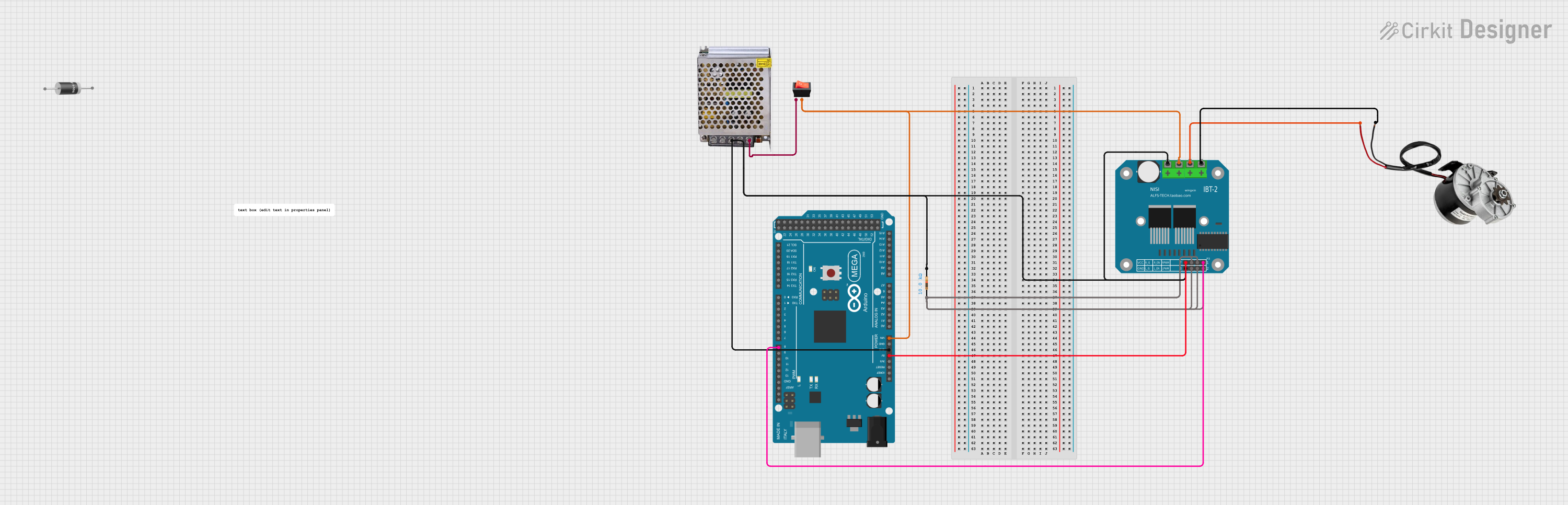
Example: Connecting to an Arduino UNO

While the PWM DC Motor Speed Control module is standalone, it can be integrated with an Arduino UNO for automated control. Below is an example of how to use an Arduino to control the module via a servo motor driver (to simulate potentiometer control):

Arduino Code Example

/*
 * Example: Controlling PWM DC Motor Speed Control with Arduino
 * This code uses a PWM signal from Arduino to simulate potentiometer control.
 * Ensure the Arduino's PWM pin is connected to the module's control input.
 */

const int pwmPin = 9; // PWM output pin connected to the module

void setup() {
  pinMode(pwmPin, OUTPUT); // Set the PWM pin as an output
}

void loop() {
  // Gradually increase motor speed
  for (int dutyCycle = 0; dutyCycle <= 255; dutyCycle++) {
    analogWrite(pwmPin, dutyCycle); // Write PWM signal to the module
    delay(20); // Small delay for smooth acceleration
  }

  delay(1000); // Run at full speed for 1 second

  // Gradually decrease motor speed
  for (int dutyCycle = 255; dutyCycle >= 0; dutyCycle--) {
    analogWrite(pwmPin, dutyCycle); // Write PWM signal to the module
    delay(20); // Small delay for smooth deceleration
  }

  delay(1000); // Pause before repeating the cycle
}

Troubleshooting and FAQs

Common Issues and Solutions

  1. Motor Does Not Spin

    • Cause: Incorrect wiring or insufficient power supply.
    • Solution: Verify all connections and ensure the power supply meets the voltage and current requirements.
  2. Motor Speed is Erratic

    • Cause: Loose connections or interference.
    • Solution: Check for secure connections and minimize electrical noise in the circuit.
  3. Controller Overheats

    • Cause: Excessive current draw or poor ventilation.
    • Solution: Ensure the motor's current draw is within the 10A limit and improve ventilation or add a heatsink.
  4. No Response to Potentiometer Adjustment

    • Cause: Faulty potentiometer or damaged module.
    • Solution: Test the potentiometer with a multimeter or replace the module if necessary.

FAQs

  • Can I use this module with a 24V motor? No, the module supports a maximum input voltage of 16V. Using a higher voltage may damage the controller.

  • Is reverse polarity protection included? Most modules do not include reverse polarity protection. Always double-check connections before powering the circuit.

  • Can I control multiple motors with this module? No, this module is designed to control a single motor. For multiple motors, use separate modules.

  • What happens if the motor stalls? A stalled motor may draw excessive current, potentially damaging the module. Use a fuse or current limiter for protection.