How to Use pcb_antenna: Examples, Pinouts, and Specs
Introduction
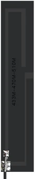
A PCB (Printed Circuit Board) antenna is an integral component designed for wireless communication systems. It is etched directly onto a PCB and is commonly used in devices where space is at a premium, such as smartphones, RFID tags, and IoT devices. The PCB antenna's primary function is to transmit and receive radio frequency (RF) signals efficiently.
Explore Projects Built with pcb_antenna

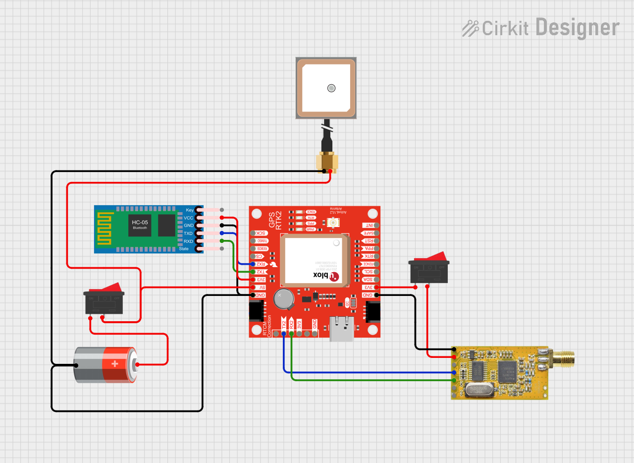

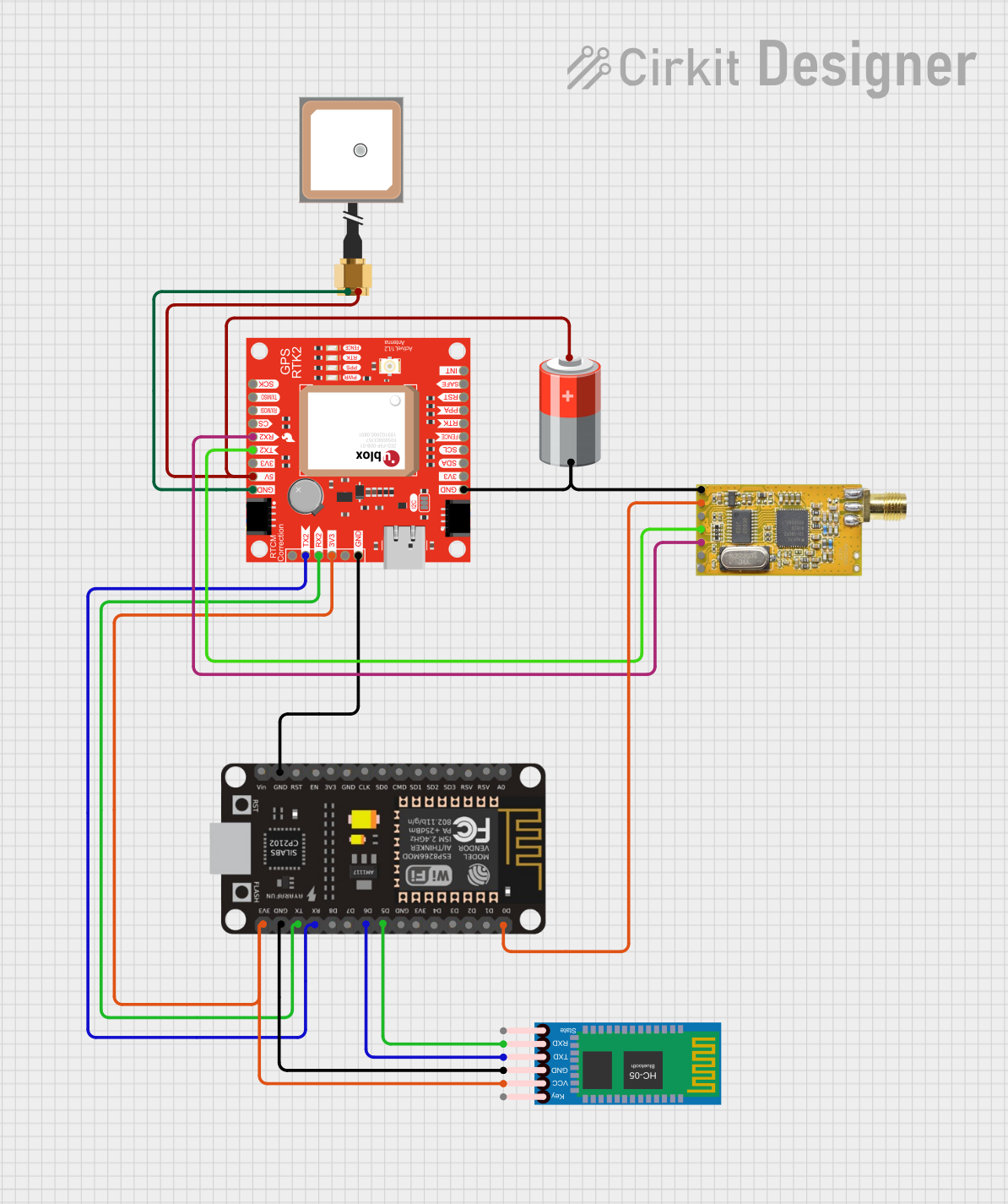
Explore Projects Built with pcb_antenna
Common Applications and Use Cases
- Wireless communication modules (Wi-Fi, Bluetooth, Zigbee)
- IoT devices (smart home sensors, wearables)
- Mobile devices (smartphones, tablets)
- RFID and NFC systems
- Remote control systems
Technical Specifications
Key Technical Details
- Frequency Range: Typically 2.4 GHz for Wi-Fi/Bluetooth applications, but can vary based on design.
- Impedance: 50 Ohms (standard for RF applications)
- Polarization: Linear
- Gain: Varies with design, typically between 1-5 dBi
- VSWR (Voltage Standing Wave Ratio): < 2:1 is desirable
Pin Configuration and Descriptions
Since a PCB antenna does not have traditional "pins" like other components, this section is replaced with key design parameters that are essential for the proper function of the antenna.
| Parameter | Description |
|---|---|
| Trace Length | The length of the antenna trace must be a specific fraction of the wavelength corresponding to the operating frequency. |
| Trace Width | The width of the antenna trace affects the impedance. |
| Substrate Material | The type of material used for the PCB can affect the antenna's performance. |
| Ground Plane Size | A larger ground plane can improve antenna performance but may not always be feasible due to space constraints. |
| Clearance Area | The area around the antenna trace that must be free of any other metal or traces. |
Usage Instructions
How to Use the Component in a Circuit
- Integration: The PCB antenna should be integrated into the design of the main PCB of the device. It is not a discrete component that can be added after the fact.
- Matching Network: A matching network may be necessary to ensure that the antenna is properly matched to the 50-ohm impedance of the RF circuitry.
- Placement: The antenna should be placed at the edge of the PCB with adequate clearance from other metal components and traces to avoid interference.
Important Considerations and Best Practices
- Keep the antenna area free from metal: Ensure that the antenna's immediate vicinity is free from any metal components or traces to prevent detuning and loss of efficiency.
- Avoid covering the antenna with a metal case: Metal cases can severely impact the performance of the antenna.
- Test and tune: After the PCB is manufactured, test the antenna's performance and tune the matching network as needed for optimal performance.
Troubleshooting and FAQs
Common Issues Users Might Face
- Reduced range or signal strength: This could be due to improper matching, a metal object near the antenna, or a poorly designed antenna trace.
- Intermittent connectivity: Check for loose connections in the matching network or issues with the RF source.
Solutions and Tips for Troubleshooting
- Ensure proper matching: Use a network analyzer to check and adjust the impedance matching.
- Check the antenna design: Verify that the antenna trace dimensions are correct for the desired frequency.
- Inspect for physical damage: Ensure that the antenna trace has not been damaged or altered during assembly.
FAQs
Q: Can I use a PCB antenna for frequencies other than 2.4 GHz? A: Yes, PCB antennas can be designed for various frequencies, but the design parameters must be adjusted accordingly.
Q: How critical is the ground plane size? A: The ground plane size is very important for antenna performance. It should be as large as possible within the constraints of the PCB design.
Q: Can I place the antenna near the edge of the PCB? A: Yes, placing the antenna near the edge can help improve performance and reduce interference from other components.
Example Code for Arduino UNO Connection
// This example assumes the use of a 2.4 GHz PCB antenna connected to an RF module
// compatible with Arduino UNO. The code provided is a simple initialization for
// communication using the RF module.

#include <SPI.h>
#include <RF24.h>

// Create an RF24 object
RF24 radio(9, 10); // CE, CSN pins

void setup() {
  Serial.begin(9600);
  // Initialize the RF module
  radio.begin();
  // Set the PA Level to LOW to prevent power supply issues
  radio.setPALevel(RF24_PA_LOW);
  // Open a writing and reading pipe on each radio, with opposite addresses
  radio.openWritingPipe(0xF0F0F0F0E1LL);
  radio.openReadingPipe(1, 0xF0F0F0F0D2LL);
  // Start the radio listening for data
  radio.startListening();
}

void loop() {
  // User code to send and receive data
}
Note: The above code is a basic example to illustrate how a PCB antenna might be used with an Arduino UNO and an RF module. The actual implementation will vary based on the specific RF module and its library. Always refer to the module's datasheet and library documentation for detailed instructions.