How to Use LTDC-X3: Examples, Pinouts, and Specs
Introduction
The LTDC-X3, manufactured by ScioSense, is a low-temperature co-fired ceramic (LTCC) component specifically designed for high-frequency applications. It is widely used in RF and microwave circuits due to its compact design, high thermal stability, and excellent performance. The LTDC-X3 is ideal for applications requiring reliable operation in demanding environments, such as telecommunications, aerospace, and industrial electronics.
Explore Projects Built with LTDC-X3


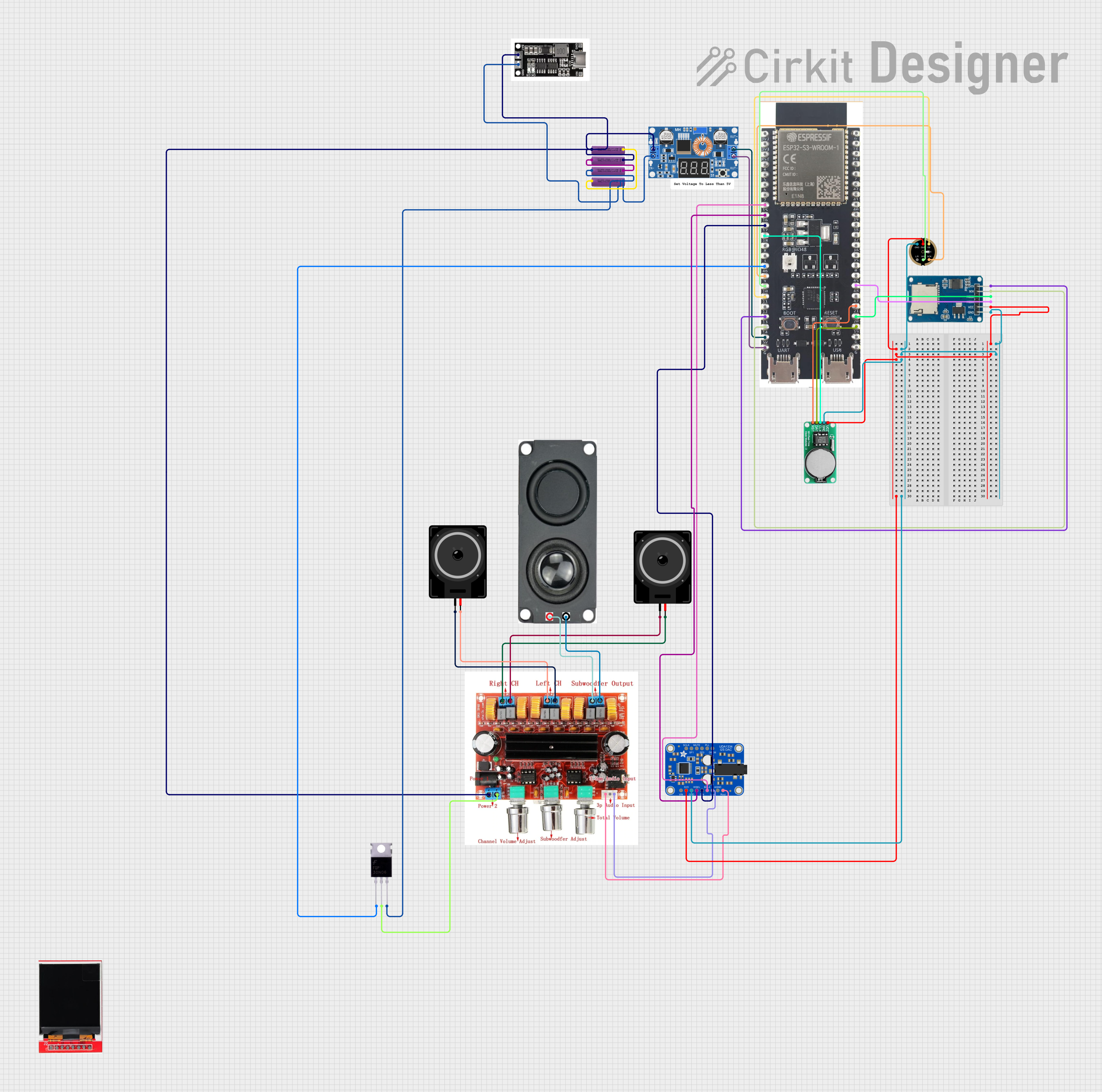
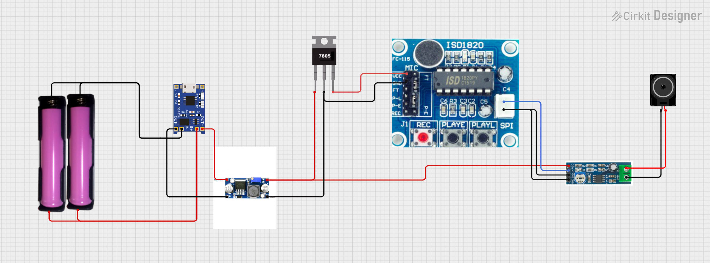
Explore Projects Built with LTDC-X3
Common Applications and Use Cases
- RF and microwave circuits
- Wireless communication systems
- Satellite and aerospace electronics
- High-frequency filters and resonators
- Industrial and automotive electronics
Technical Specifications
The LTDC-X3 is engineered to meet the demands of high-frequency applications. Below are its key technical specifications:
| Parameter | Value |
|---|---|
| Manufacturer Part ID | LTDC-X3 |
| Manufacturer | ScioSense |
| Material | Low-Temperature Co-Fired Ceramic (LTCC) |
| Frequency Range | Up to 10 GHz |
| Thermal Stability | ±0.1% over -40°C to +125°C |
| Dielectric Constant (εr) | 7.8 ± 0.2 |
| Loss Tangent (tan δ) | ≤ 0.001 |
| Operating Temperature | -40°C to +125°C |
| Dimensions | 2.0 mm x 1.2 mm x 0.8 mm |
| Mounting Type | Surface Mount Technology (SMT) |
Pin Configuration and Descriptions
The LTDC-X3 is a surface-mount component with the following pin configuration:
| Pin Number | Pin Name | Description |
|---|---|---|
| 1 | Input | RF signal input |
| 2 | Ground | Ground connection for stability |
| 3 | Output | RF signal output |
Usage Instructions
The LTDC-X3 is designed for seamless integration into high-frequency circuits. Follow these steps and best practices to ensure optimal performance:
How to Use the LTDC-X3 in a Circuit
- Placement: Mount the LTDC-X3 on a PCB using standard Surface Mount Technology (SMT) techniques. Ensure proper alignment with the PCB pads.
- Connections:
- Connect the Input pin to the RF signal source.
- Connect the Ground pin to the PCB ground plane for stability.
- Connect the Output pin to the desired RF circuit or load.
- Impedance Matching: Use appropriate matching networks to ensure impedance compatibility with the surrounding circuitry.
- Thermal Management: Ensure adequate thermal dissipation by designing a PCB with a proper ground plane and thermal vias.
Important Considerations and Best Practices
- Frequency Range: Verify that the operating frequency of your circuit is within the LTDC-X3's specified range (up to 10 GHz).
- Soldering: Use reflow soldering techniques with a maximum peak temperature of 260°C to avoid damaging the component.
- PCB Design: Minimize parasitic inductance and capacitance by keeping traces short and using a high-quality PCB substrate.
- Testing: Use a network analyzer to verify the performance of the LTDC-X3 in your circuit.
Example: Connecting LTDC-X3 to an Arduino UNO
While the LTDC-X3 is not directly compatible with microcontrollers like the Arduino UNO due to its high-frequency nature, it can be used in conjunction with RF modules or circuits that interface with the Arduino. Below is an example of how to use the LTDC-X3 in an RF filter circuit connected to an Arduino-controlled RF module:
// Example: Controlling an RF module with Arduino UNO
// Note: The LTDC-X3 is used in the RF filter circuit, not directly with Arduino

#include <SPI.h>  // Include SPI library for RF module communication

#define RF_MODULE_CS 10  // Chip Select pin for the RF module

void setup() {
  pinMode(RF_MODULE_CS, OUTPUT);  // Set CS pin as output
  SPI.begin();  // Initialize SPI communication

  // Initialize the RF module
  digitalWrite(RF_MODULE_CS, LOW);  // Select the RF module
  SPI.transfer(0x01);  // Example command to initialize the module
  digitalWrite(RF_MODULE_CS, HIGH);  // Deselect the RF module
}

void loop() {
  // Example: Send data via the RF module
  digitalWrite(RF_MODULE_CS, LOW);  // Select the RF module
  SPI.transfer(0x02);  // Example command to send data
  digitalWrite(RF_MODULE_CS, HIGH);  // Deselect the RF module

  delay(1000);  // Wait for 1 second
}
Troubleshooting and FAQs
Common Issues and Solutions
Issue: Poor performance at high frequencies.
- Solution: Check for impedance mismatches and ensure proper PCB layout with minimal parasitics.
Issue: Overheating during operation.
- Solution: Verify that the operating temperature is within the specified range and improve thermal dissipation on the PCB.
Issue: Signal loss or distortion.
- Solution: Ensure proper soldering and connections. Use a network analyzer to identify and resolve issues in the RF path.
FAQs
Q1: Can the LTDC-X3 be used in low-frequency applications?
A1: The LTDC-X3 is optimized for high-frequency applications (up to 10 GHz). While it may function at lower frequencies, its performance may not be ideal.
Q2: What type of PCB substrate is recommended for the LTDC-X3?
A2: Use a high-frequency PCB substrate, such as Rogers or FR4 with low loss, to ensure optimal performance.
Q3: Is the LTDC-X3 compatible with through-hole mounting?
A3: No, the LTDC-X3 is designed for Surface Mount Technology (SMT) only.
Q4: How do I test the LTDC-X3 in my circuit?
A4: Use a vector network analyzer (VNA) to measure parameters such as insertion loss, return loss, and impedance matching.
By following this documentation, you can effectively integrate the LTDC-X3 into your high-frequency designs and achieve reliable performance.