How to Use MY2N: Examples, Pinouts, and Specs
Introduction
The MY2N is a relay component manufactured by SMKN1KRAS with the part ID "A". It is designed for switching applications in electronic circuits. This relay features a Double Pole Double Throw (DPDT) configuration, enabling it to control two independent circuits simultaneously. The MY2N operates using an electromagnetic coil that, when energized, toggles the relay contacts to open or close the connected circuits.
Explore Projects Built with MY2N
Explore Projects Built with MY2N
Common Applications
- Industrial automation systems
- Home appliances
- Motor control circuits
- Signal switching in communication systems
- Power management in electronic devices
Technical Specifications
Key Specifications
| Parameter | Value |
|---|---|
| Manufacturer | SMKN1KRAS |
| Part ID | A |
| Relay Type | Electromagnetic DPDT |
| Coil Voltage (Nominal) | 12V DC / 24V DC / 110V AC |
| Coil Resistance | Varies by voltage (e.g., 400Ω for 12V DC) |
| Contact Rating | 5A at 250V AC / 30V DC |
| Contact Material | Silver alloy |
| Switching Mechanism | Electromagnetic |
| Insulation Resistance | ≥ 100MΩ at 500V DC |
| Dielectric Strength | 1500V AC for 1 minute |
| Operating Temperature | -40°C to +70°C |
| Mechanical Life | 10 million operations |
| Electrical Life | 100,000 operations |
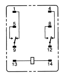
Pin Configuration
The MY2N relay has 8 pins arranged in a standard DPDT configuration. Below is the pinout description:
| Pin Number | Description |
|---|---|
| 1 | Coil Terminal 1 (Positive) |
| 2 | Coil Terminal 2 (Negative) |
| 3 | Common Contact 1 (COM1) |
| 4 | Normally Open Contact 1 (NO1) |
| 5 | Normally Closed Contact 1 (NC1) |
| 6 | Common Contact 2 (COM2) |
| 7 | Normally Open Contact 2 (NO2) |
| 8 | Normally Closed Contact 2 (NC2) |
Usage Instructions
How to Use the MY2N in a Circuit
- Power the Coil: Connect the coil terminals (pins 1 and 2) to the appropriate voltage source. Ensure the voltage matches the relay's rated coil voltage (e.g., 12V DC).
- Connect the Load:
- For the first circuit, connect the load to pins 3 (COM1), 4 (NO1), and 5 (NC1).
- For the second circuit, connect the load to pins 6 (COM2), 7 (NO2), and 8 (NC2).
- Switching Behavior:
- When the coil is not energized, the COM pins are connected to the NC pins.
- When the coil is energized, the COM pins are connected to the NO pins.
- Protection: Add a flyback diode across the coil terminals to protect the circuit from voltage spikes caused by the relay's inductive load.
Best Practices
- Always verify the relay's coil voltage and contact ratings before use.
- Use a proper heat sink or cooling mechanism if the relay operates in high-temperature environments.
- Avoid exceeding the relay's electrical life by operating it within its rated current and voltage limits.
- For microcontroller-based applications, use a transistor or relay driver circuit to control the relay.
Example: Connecting MY2N to an Arduino UNO
Below is an example of how to control the MY2N relay using an Arduino UNO:
// Define the pin connected to the relay's coil
const int relayPin = 7;

void setup() {
  pinMode(relayPin, OUTPUT); // Set the relay pin as an output
  digitalWrite(relayPin, LOW); // Ensure the relay is off initially
}

void loop() {
  digitalWrite(relayPin, HIGH); // Energize the relay coil
  delay(1000); // Keep the relay on for 1 second
  digitalWrite(relayPin, LOW); // De-energize the relay coil
  delay(1000); // Keep the relay off for 1 second
}
Note: Use a transistor (e.g., 2N2222) and a flyback diode (e.g., 1N4007) to interface the relay with the Arduino, as the Arduino's GPIO pins cannot directly drive the relay.
Troubleshooting and FAQs
Common Issues and Solutions
Relay Not Switching:
- Cause: Insufficient coil voltage or current.
- Solution: Verify the power supply voltage and ensure it matches the relay's rated coil voltage.
Contacts Sticking:
- Cause: Overloading the relay contacts.
- Solution: Ensure the load does not exceed the relay's contact rating.
Excessive Heat:
- Cause: Prolonged operation at high current.
- Solution: Use a heat sink or reduce the load current.
Noise or Chattering:
- Cause: Unstable power supply or insufficient driving current.
- Solution: Use a stable power source and ensure proper driving circuitry.
FAQs
Q1: Can the MY2N relay switch both AC and DC loads?
A1: Yes, the MY2N can switch both AC and DC loads, provided the load voltage and current are within the relay's contact ratings.
Q2: What is the purpose of the flyback diode?
A2: The flyback diode protects the driving circuit from voltage spikes generated when the relay coil is de-energized.
Q3: Can I use the MY2N relay for high-frequency switching?
A3: No, the MY2N is not suitable for high-frequency switching due to its mechanical nature. Use a solid-state relay for such applications.
Q4: How do I test if the relay is functioning?
A4: Apply the rated coil voltage to pins 1 and 2, and check if the COM pins switch between the NO and NC pins using a multimeter.