How to Use STEP DOWN: Examples, Pinouts, and Specs
Introduction
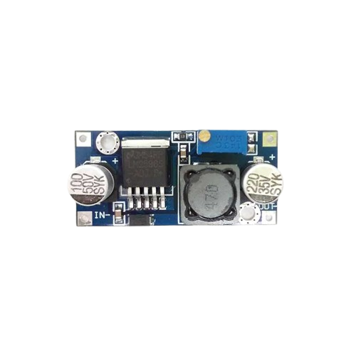
A step-down converter, also known as a buck converter, is a type of DC-DC converter designed to reduce voltage from a higher level to a lower level while increasing current. It is widely used in power supply applications due to its high efficiency and ability to handle varying input voltages. This component is essential in scenarios where devices require a stable, lower voltage than the input source provides, such as powering microcontrollers, LEDs, or other low-voltage electronics.
Explore Projects Built with STEP DOWN


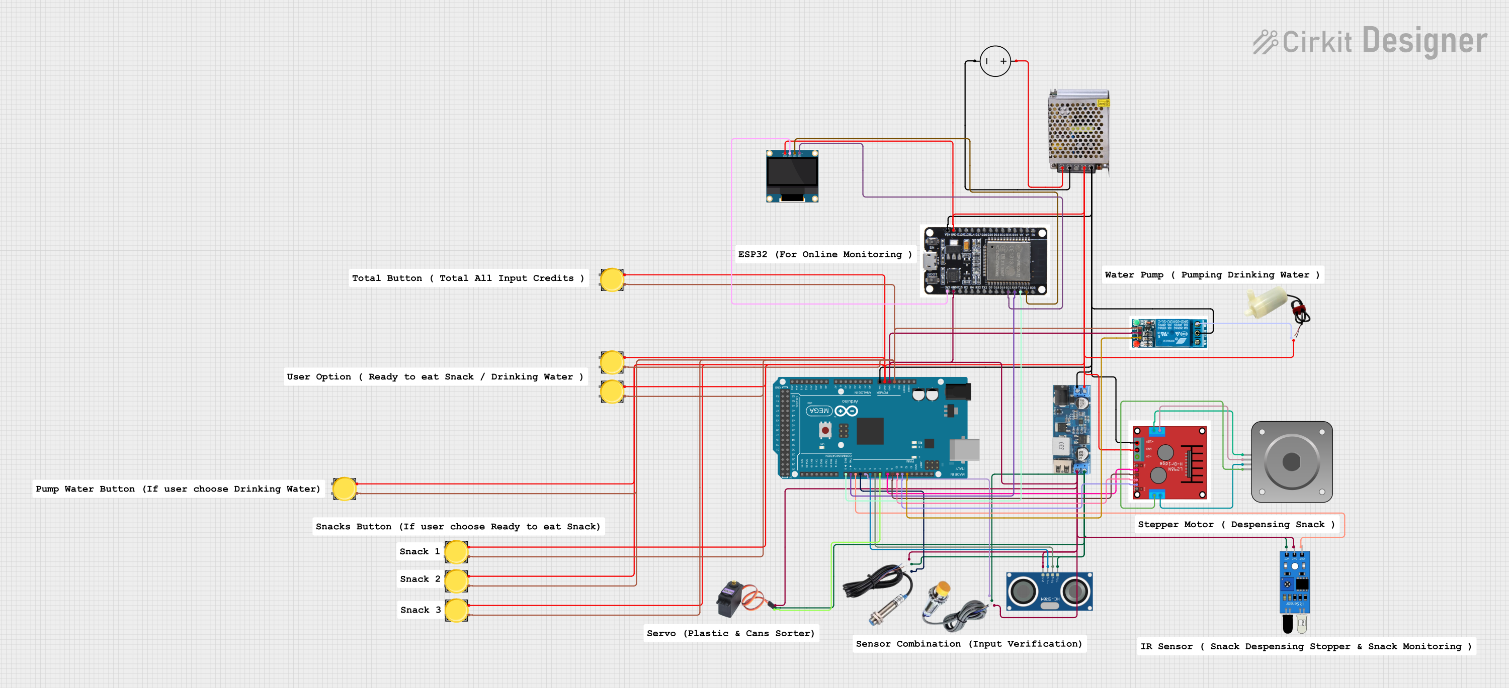
Explore Projects Built with STEP DOWN
Common Applications and Use Cases
- Powering microcontrollers (e.g., Arduino, Raspberry Pi) from higher voltage sources.
- Battery-powered devices requiring efficient voltage regulation.
- LED drivers and lighting systems.
- Industrial and automotive electronics.
- Renewable energy systems (e.g., solar panels).
Technical Specifications
Below are the general technical specifications for a typical step-down converter. Note that specific models may vary, so always refer to the datasheet of the exact component you are using.
| Parameter | Value |
|---|---|
| Input Voltage Range | 4.5V to 40V |
| Output Voltage Range | 1.2V to 37V (adjustable) |
| Output Current | Up to 3A (depending on the model) |
| Efficiency | Up to 90-95% |
| Switching Frequency | 150 kHz (typical) |
| Operating Temperature | -40°C to +85°C |
Pin Configuration and Descriptions
The pinout of a step-down converter module (e.g., LM2596-based module) is as follows:
| Pin Name | Description |
|---|---|
| VIN | Input voltage pin. Connect the higher voltage source here (e.g., 12V battery). |
| GND | Ground pin. Connect to the ground of the circuit. |
| VOUT | Output voltage pin. Provides the regulated lower voltage. |
| ADJ (optional) | Adjustment pin for setting the output voltage (on adjustable models). |
Usage Instructions
How to Use the Component in a Circuit
Connect the Input Voltage (VIN):
Attach the higher voltage source (e.g., a 12V battery or power supply) to the VIN pin. Ensure the input voltage is within the specified range of the step-down converter.Connect the Ground (GND):
Connect the GND pin to the ground of your circuit. This is essential for proper operation.Set the Output Voltage (if adjustable):
- For adjustable step-down converters, use the onboard potentiometer to set the desired output voltage.
- Measure the output voltage at the VOUT pin using a multimeter while adjusting the potentiometer.
Connect the Load to VOUT:
Attach the device or circuit requiring the lower voltage to the VOUT pin. Ensure the load does not exceed the maximum current rating of the converter.Power On and Test:
Turn on the input power source and verify the output voltage using a multimeter. Ensure the output voltage matches the requirements of your load.
Important Considerations and Best Practices
- Input Voltage: Always ensure the input voltage is within the specified range of the step-down converter.
- Heat Dissipation: For high-current applications, the converter may generate heat. Use a heatsink or active cooling if necessary.
- Output Filtering: Some applications may require additional capacitors at the output to reduce noise and ripple.
- Polarity: Double-check the polarity of the input and output connections to avoid damaging the module.
- Load Current: Ensure the load does not exceed the maximum current rating of the converter.
Example: Using a Step-Down Converter with Arduino UNO
Below is an example of how to use a step-down converter to power an Arduino UNO from a 12V source:
- Connect the 12V source to the VIN pin of the step-down converter.
- Adjust the output voltage to 5V using the onboard potentiometer.
- Connect the VOUT pin of the converter to the 5V pin of the Arduino UNO.
- Connect the GND pin of the converter to the GND pin of the Arduino UNO.
// Example Arduino code to blink an LED
// Ensure the Arduino is powered via the step-down converter (5V output).

int ledPin = 13; // Pin connected to the onboard LED

void setup() {
  pinMode(ledPin, OUTPUT); // Set the LED pin as an output
}

void loop() {
  digitalWrite(ledPin, HIGH); // Turn the LED on
  delay(1000);                // Wait for 1 second
  digitalWrite(ledPin, LOW);  // Turn the LED off
  delay(1000);                // Wait for 1 second
}
Troubleshooting and FAQs
Common Issues and Solutions
No Output Voltage:
- Cause: Incorrect input voltage or loose connections.
- Solution: Verify the input voltage is within the specified range and check all connections.
Output Voltage is Incorrect:
- Cause: Potentiometer not adjusted correctly or load exceeds the converter's capacity.
- Solution: Re-adjust the potentiometer and ensure the load is within the current rating.
Excessive Heat:
- Cause: High current draw or insufficient cooling.
- Solution: Add a heatsink or reduce the load current.
Noise or Ripple in Output Voltage:
- Cause: Insufficient filtering or high-frequency noise.
- Solution: Add additional capacitors (e.g., 100µF electrolytic and 0.1µF ceramic) at the output.
FAQs
Q: Can I use a step-down converter to power a 3.3V device?
A: Yes, as long as the converter's output voltage is adjustable to 3.3V and the device's current requirements are within the converter's capacity.
Q: What happens if I reverse the input polarity?
A: Most step-down converters do not have reverse polarity protection and may be damaged. Always double-check the polarity before powering the module.
Q: Can I use a step-down converter with an AC input?
A: No, step-down converters are designed for DC input only. Use a rectifier circuit to convert AC to DC before using the converter.
Q: How do I calculate the efficiency of the converter?
A: Efficiency (%) = (Output Power / Input Power) × 100. Measure the input and output voltages and currents to calculate power.