How to Use HUB75E: Examples, Pinouts, and Specs
Introduction
The HUB75E is a standardized interface designed for connecting LED displays, particularly in large-scale video walls and digital signage applications. It serves as a communication bridge between the display controller and LED modules, enabling efficient data transfer and precise control of pixel information. The HUB75E interface is widely used in RGB LED matrices due to its simplicity, scalability, and ability to handle high-speed data transmission.
Explore Projects Built with HUB75E

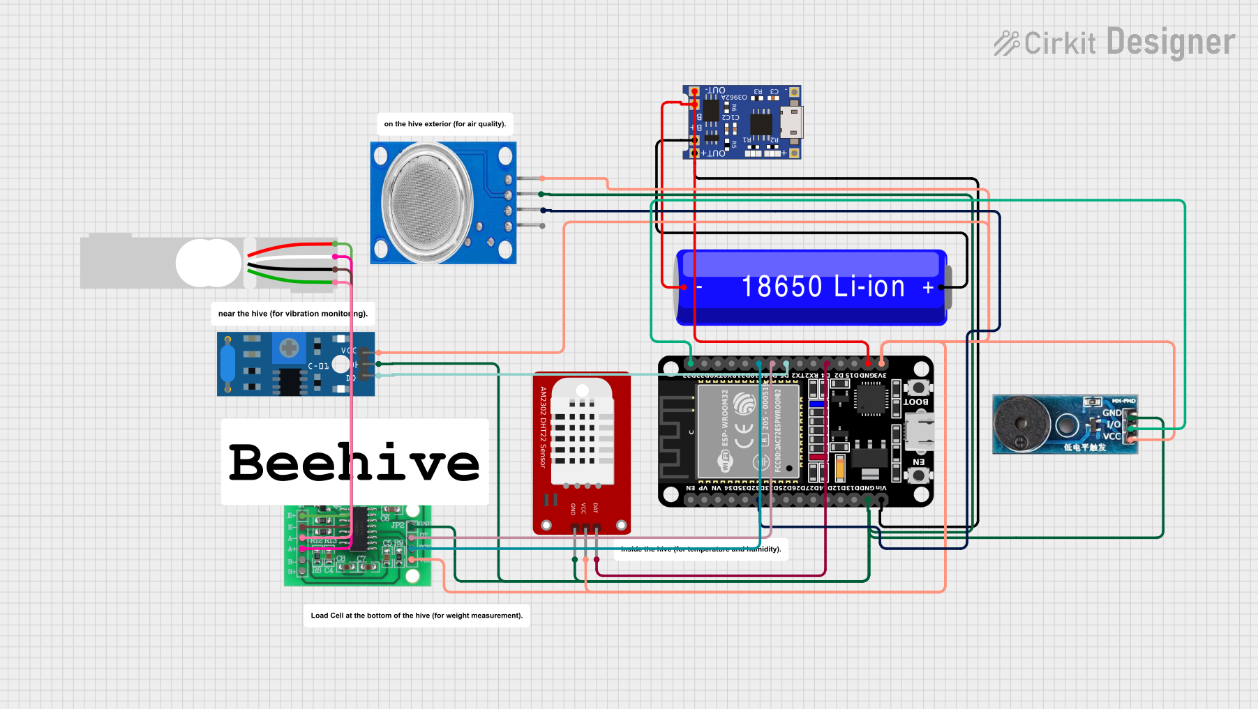

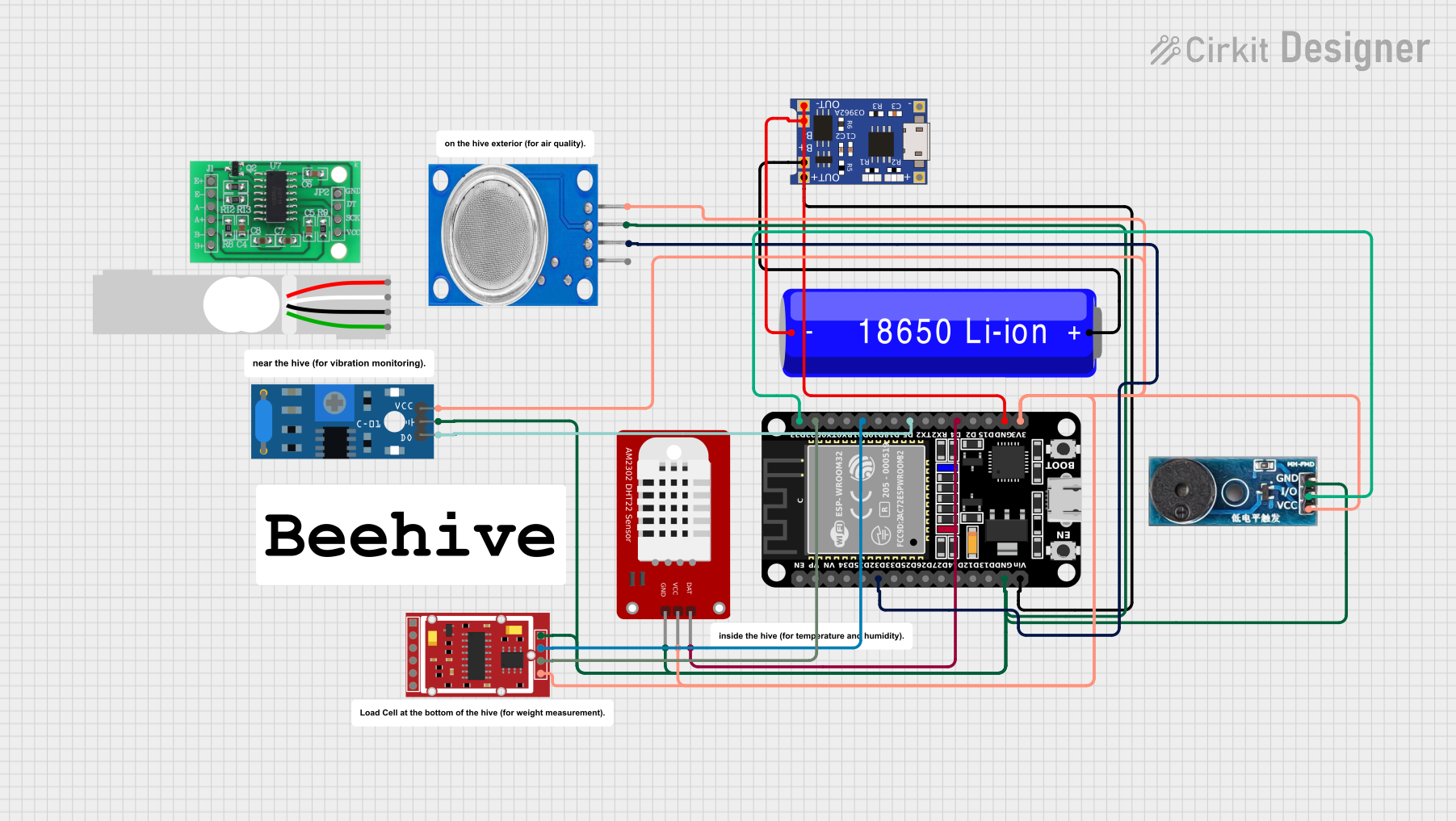
Explore Projects Built with HUB75E
Common Applications and Use Cases
- Large-scale video walls in stadiums, shopping malls, and public spaces
- Digital signage for advertising and information display
- RGB LED matrix displays for animations, text, and graphics
- Interactive LED panels for events and exhibitions
Technical Specifications
Key Technical Details
- Voltage Range: 3.3V to 5V (logic level)
- Data Protocol: Parallel data transmission
- Supported LED Configurations: RGB (1/8, 1/16, or 1/32 scan modes)
- Connector Type: 16-pin IDC (dual-row)
- Maximum Refresh Rate: Up to 1920Hz (depending on the controller and LED module)
- Pixel Control: Supports up to 64x64 pixels per module
- Signal Type: TTL (Transistor-Transistor Logic)
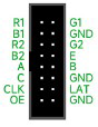
Pin Configuration and Descriptions
The HUB75E interface uses a 16-pin IDC connector with the following pinout:
| Pin | Name | Description |
|---|---|---|
| 1 | R0 | Red data for the first row of LEDs |
| 2 | G0 | Green data for the first row of LEDs |
| 3 | B0 | Blue data for the first row of LEDs |
| 4 | GND | Ground connection |
| 5 | R1 | Red data for the second row of LEDs |
| 6 | G1 | Green data for the second row of LEDs |
| 7 | B1 | Blue data for the second row of LEDs |
| 8 | GND | Ground connection |
| 9 | A | Row address selection bit 0 |
| 10 | B | Row address selection bit 1 |
| 11 | C | Row address selection bit 2 |
| 12 | D | Row address selection bit 3 |
| 13 | E | Row address selection bit 4 (used in larger matrices, e.g., 64x64) |
| 14 | CLK | Clock signal for synchronizing data transfer |
| 15 | LAT | Latch signal to update the LED display |
| 16 | OE | Output enable signal (active low, controls brightness and blanking of LEDs) |
Usage Instructions
How to Use the HUB75E in a Circuit
- Connect the HUB75E Interface: Use a 16-pin ribbon cable to connect the HUB75E interface on the LED module to the corresponding output on the LED controller board.
- Power the LED Module: Ensure the LED module is powered with the appropriate voltage (typically 5V). Connect the ground (GND) of the power supply to the GND pin of the HUB75E interface.
- Send Data Signals: Use a compatible LED controller (e.g., Raspberry Pi, Arduino, or dedicated LED driver board) to send RGB data, clock, latch, and row address signals to the HUB75E interface.
- Configure the Controller: Set the scan mode (e.g., 1/16 or 1/32) and resolution in the controller software to match the LED module specifications.
Important Considerations and Best Practices
- Signal Integrity: Use short and high-quality ribbon cables to minimize signal degradation, especially for high refresh rates.
- Power Supply: Ensure the power supply can handle the current requirements of the LED module. Large displays may require multiple power supplies.
- Heat Management: LED modules can generate significant heat. Use proper ventilation or cooling mechanisms to prevent overheating.
- Scan Mode Compatibility: Verify that the controller supports the scan mode of your LED module (e.g., 1/16 or 1/32).
- Arduino Compatibility: The HUB75E interface can be controlled using an Arduino UNO with libraries like
Adafruit_GFXandPxMatrix.
Example Arduino Code
Below is an example of how to control a HUB75E-based RGB LED matrix using an Arduino UNO and the PxMatrix library:
#include <PxMatrix.h> // Include the PxMatrix library

// Define the display size (e.g., 32x16 matrix)
#define MATRIX_WIDTH 32
#define MATRIX_HEIGHT 16

// Define the pins connected to the HUB75E interface
#define P_LAT 10  // Latch pin
#define P_A  A0   // Row address A
#define P_B  A1   // Row address B
#define P_C  A2   // Row address C
#define P_D  A3   // Row address D
#define P_E  A4   // Row address E (if applicable)
#define P_OE 9    // Output enable pin

// Create a PxMatrix object
PxMatrix display(MATRIX_WIDTH, MATRIX_HEIGHT, P_LAT, P_OE, P_A, P_B, P_C, P_D);

// Setup function
void setup() {
  display.begin(16); // Initialize the display with a 1/16 scan rate
  display.setBrightness(100); // Set brightness (0-255)
}

// Loop function
void loop() {
  display.fillScreen(display.color565(255, 0, 0)); // Fill screen with red
  delay(1000); // Wait for 1 second
  display.fillScreen(display.color565(0, 255, 0)); // Fill screen with green
  delay(1000); // Wait for 1 second
  display.fillScreen(display.color565(0, 0, 255)); // Fill screen with blue
  delay(1000); // Wait for 1 second
}
Troubleshooting and FAQs
Common Issues and Solutions
LEDs Not Lighting Up:
- Check the power supply and ensure the voltage matches the LED module's requirements.
- Verify all connections between the controller and the HUB75E interface.
Flickering or Incorrect Colors:
- Ensure the ribbon cable is securely connected and not damaged.
- Check the scan mode configuration in the controller software.
Low Brightness:
- Increase the brightness setting in the controller software or Arduino code.
- Verify that the power supply can provide sufficient current.
Display Not Updating:
- Confirm that the clock (CLK) and latch (LAT) signals are being sent correctly.
- Check the row address (A, B, C, D, E) connections.
FAQs
Can I use the HUB75E with a Raspberry Pi? Yes, the HUB75E interface is compatible with Raspberry Pi using libraries like
rpi-rgb-led-matrix.What is the difference between HUB75 and HUB75E? The HUB75E interface includes an additional row address pin (E) for larger LED matrices, such as 64x64 displays.
How do I daisy-chain multiple LED modules? Connect the output of one module to the input of the next using ribbon cables. Ensure the controller supports the total resolution.
What is the maximum cable length for HUB75E? For reliable operation, keep the cable length under 1 meter. Use signal boosters for longer distances.