How to Use DIP Switch (8 Position): Examples, Pinouts, and Specs
Introduction
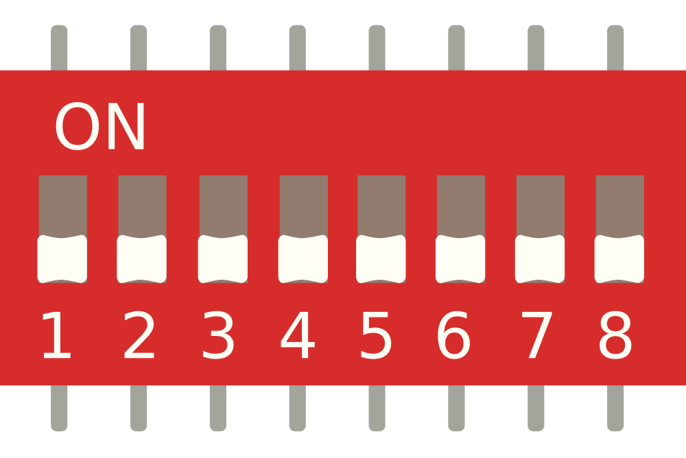
A DIP switch (Dual In-Line Package switch) with 8 individual switches is a compact and versatile component used for setting configurations or options in electronic devices. Each of the 8 switches can be toggled independently to represent binary states (ON or OFF), making it ideal for applications requiring manual input or mode selection.
Explore Projects Built with DIP Switch (8 Position)
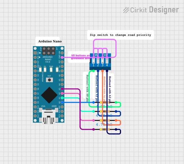
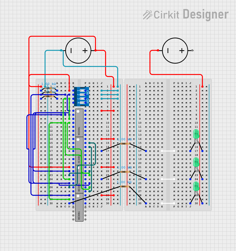

Explore Projects Built with DIP Switch (8 Position)
Common Applications and Use Cases
- Configuring hardware settings in embedded systems
- Setting device addresses in communication protocols (e.g., I2C, RS-485)
- Enabling or disabling features in electronic circuits
- Debugging and testing circuits by toggling specific inputs
- Mode selection in microcontroller-based projects
Technical Specifications
The DIP switch (8 position) is designed for low-power, low-voltage applications and is compatible with standard breadboards and PCBs.
Key Technical Details
| Parameter | Value |
|---|---|
| Number of Switches | 8 |
| Switch Type | SPST (Single Pole Single Throw) |
| Voltage Rating | 24V DC (maximum) |
| Current Rating | 25mA (maximum) |
| Contact Resistance | ≤ 100 mΩ |
| Insulation Resistance | ≥ 100 MΩ |
| Operating Temperature | -20°C to +70°C |
| Actuation Force | 200-500 gf |
| Mounting Type | Through-hole or surface mount |
Pin Configuration and Descriptions
The DIP switch has 16 pins in total, with each switch having two pins (one input and one output). The pin configuration is as follows:
| Pin Number | Description |
|---|---|
| 1-2 | Switch 1 (Input and Output) |
| 3-4 | Switch 2 (Input and Output) |
| 5-6 | Switch 3 (Input and Output) |
| 7-8 | Switch 4 (Input and Output) |
| 9-10 | Switch 5 (Input and Output) |
| 11-12 | Switch 6 (Input and Output) |
| 13-14 | Switch 7 (Input and Output) |
| 15-16 | Switch 8 (Input and Output) |
Note: When a switch is toggled ON, the corresponding pins are connected, allowing current to flow. When toggled OFF, the pins are disconnected.
Usage Instructions
How to Use the Component in a Circuit
Mounting the DIP Switch:
- Insert the DIP switch into a breadboard or solder it onto a PCB.
- Ensure proper alignment of the pins to avoid misconnection.
Connecting the Switches:
- Connect one pin of each switch to a voltage source (e.g., 5V or 3.3V).
- Connect the other pin to the input of a microcontroller or circuit component.
- Use pull-down resistors (typically 10kΩ) on the input pins to ensure a stable LOW state when the switch is OFF.
Reading the Switch States:
- When a switch is ON, the corresponding input pin will read HIGH.
- When a switch is OFF, the pull-down resistor will pull the input pin to LOW.
Important Considerations and Best Practices
- Avoid exceeding the voltage and current ratings to prevent damage to the switch.
- Use a multimeter to verify the continuity of each switch before integrating it into a circuit.
- For microcontroller-based projects, debounce the switch inputs in software to avoid false readings caused by mechanical bouncing.
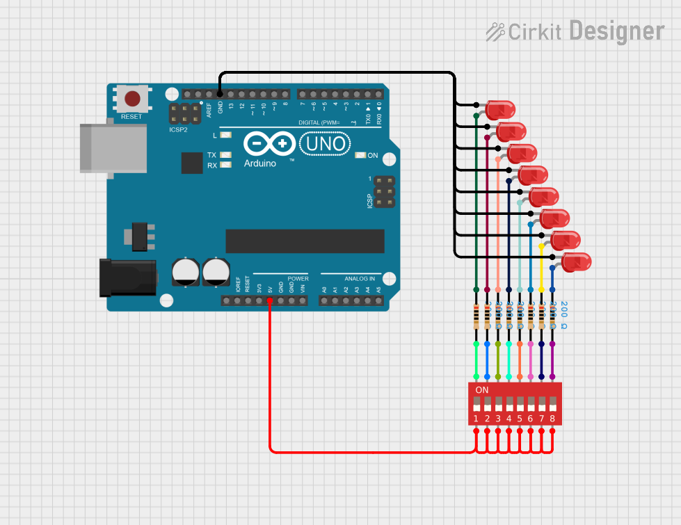
Example: Using a DIP Switch with Arduino UNO
The following example demonstrates how to read the states of an 8-position DIP switch using an Arduino UNO.
// Define the pins connected to the DIP switch
const int dipSwitchPins[8] = {2, 3, 4, 5, 6, 7, 8, 9};

void setup() {
  // Initialize serial communication for debugging
  Serial.begin(9600);

  // Set DIP switch pins as inputs with pull-down resistors
  for (int i = 0; i < 8; i++) {
    pinMode(dipSwitchPins[i], INPUT_PULLDOWN);
  }
}

void loop() {
  // Read and print the state of each switch
  Serial.print("DIP Switch States: ");
  for (int i = 0; i < 8; i++) {
    int state = digitalRead(dipSwitchPins[i]);
    Serial.print(state); // Print 1 for ON, 0 for OFF
    Serial.print(" ");
  }
  Serial.println(); // Move to the next line
  delay(500); // Wait for 500ms before reading again
}
Note: The INPUT_PULLDOWN mode is used to ensure stable LOW states when switches are OFF. If your Arduino board does not support INPUT_PULLDOWN, use external pull-down resistors.
Troubleshooting and FAQs
Common Issues and Solutions
Switch Not Responding:
- Cause: Poor connection or damaged switch.
- Solution: Check the solder joints or breadboard connections. Test the switch with a multimeter.
Incorrect Readings:
- Cause: Mechanical bouncing or lack of pull-down resistors.
- Solution: Implement software debouncing or add external pull-down resistors.
Overheating or Damage:
- Cause: Exceeding voltage or current ratings.
- Solution: Ensure the voltage and current are within the specified limits.
Switch Feels Stiff or Loose:
- Cause: Physical wear or manufacturing defect.
- Solution: Replace the DIP switch if it is physically damaged.
FAQs
Q: Can I use the DIP switch for high-power applications?
A: No, the DIP switch is designed for low-power applications with a maximum current rating of 25mA.
Q: How do I clean a dirty or oxidized DIP switch?
A: Use a small amount of contact cleaner and gently toggle the switches to remove dirt or oxidation.
Q: Can I use fewer than 8 switches in my circuit?
A: Yes, you can use as many switches as needed. Leave unused switches disconnected.
Q: Is the DIP switch compatible with 3.3V systems?
A: Yes, the DIP switch works with both 3.3V and 5V systems, as long as the voltage and current ratings are not exceeded.