Cirkit Designer Logo
Cirkit Designer
Your all-in-one circuit design IDE
Home / 
Component Documentation

How to Use 3s bms: Examples, Pinouts, and Specs

Image of 3s bms
Cirkit Designer LogoDesign with 3s bms in Cirkit Designer

Introduction

A 3S BMS (Battery Management System) is a circuit protection and monitoring device designed specifically for a 3-cell lithium-ion or lithium-polymer battery pack. It ensures the safe operation of the battery pack by balancing cell voltages, preventing overcharging, overdischarging, and overcurrent situations. This component is crucial for maintaining the longevity and safety of battery packs used in various applications.

Explore Projects Built with 3s bms

Use Cirkit Designer to design, explore, and prototype these projects online. Some projects support real-time simulation. Click "Open Project" to start designing instantly!
18650 Li-ion Battery-Powered BMS with Boost Converter and 5V Adapter
Image of dog: A project utilizing 3s bms in a practical application
This circuit consists of three 18650 Li-ion batteries connected in parallel to a Battery Management System (BMS), which ensures safe charging and discharging of the batteries. The BMS output is connected to a 5V adapter and an XL6009E1 Boost Converter, indicating that the circuit is designed to provide a regulated power supply, likely stepping up the voltage to a required level for downstream electronics.
Cirkit Designer LogoOpen Project in Cirkit Designer
Battery-Powered 18650 Li-ion Charger with USB Output and Adjustable Voltage Regulator
Image of Breadboard: A project utilizing 3s bms in a practical application
This circuit is a battery management and power supply system that uses three 3.7V batteries connected to a 3S 10A Li-ion 18650 Charger Protection Board Module for balanced charging and protection. The system includes a TP4056 Battery Charging Protection Module for additional charging safety, a Step Up Boost Power Converter to regulate and boost the voltage, and a USB regulator to provide a stable 5V output, controlled by a push switch.
Cirkit Designer LogoOpen Project in Cirkit Designer
18650 Li-ion Battery Pack with BMS for 5V Power Supply
Image of battary: A project utilizing 3s bms in a practical application
This circuit consists of a battery management system (BMS) connected to a series of 18650 Li-ion batteries arranged in a 4S configuration to provide a regulated output voltage. The BMS ensures safe charging and discharging of the batteries, while a connector provides a 5V output for external devices.
Cirkit Designer LogoOpen Project in Cirkit Designer
Battery-Powered Servo Control System with 2S 30A BMS and TP5100 Charger
Image of servo power supply: A project utilizing 3s bms in a practical application
This circuit is a battery management and charging system for a 2S lithium-ion battery pack, which powers multiple MG996R servos. The TP5100 module charges the battery pack from a 12V power supply, while the 2S 30A BMS ensures safe operation and distribution of power to the servos.
Cirkit Designer LogoOpen Project in Cirkit Designer

Explore Projects Built with 3s bms

Use Cirkit Designer to design, explore, and prototype these projects online. Some projects support real-time simulation. Click "Open Project" to start designing instantly!
Image of dog: A project utilizing 3s bms in a practical application
18650 Li-ion Battery-Powered BMS with Boost Converter and 5V Adapter
This circuit consists of three 18650 Li-ion batteries connected in parallel to a Battery Management System (BMS), which ensures safe charging and discharging of the batteries. The BMS output is connected to a 5V adapter and an XL6009E1 Boost Converter, indicating that the circuit is designed to provide a regulated power supply, likely stepping up the voltage to a required level for downstream electronics.
Cirkit Designer LogoOpen Project in Cirkit Designer
Image of Breadboard: A project utilizing 3s bms in a practical application
Battery-Powered 18650 Li-ion Charger with USB Output and Adjustable Voltage Regulator
This circuit is a battery management and power supply system that uses three 3.7V batteries connected to a 3S 10A Li-ion 18650 Charger Protection Board Module for balanced charging and protection. The system includes a TP4056 Battery Charging Protection Module for additional charging safety, a Step Up Boost Power Converter to regulate and boost the voltage, and a USB regulator to provide a stable 5V output, controlled by a push switch.
Cirkit Designer LogoOpen Project in Cirkit Designer
Image of battary: A project utilizing 3s bms in a practical application
18650 Li-ion Battery Pack with BMS for 5V Power Supply
This circuit consists of a battery management system (BMS) connected to a series of 18650 Li-ion batteries arranged in a 4S configuration to provide a regulated output voltage. The BMS ensures safe charging and discharging of the batteries, while a connector provides a 5V output for external devices.
Cirkit Designer LogoOpen Project in Cirkit Designer
Image of servo power supply: A project utilizing 3s bms in a practical application
Battery-Powered Servo Control System with 2S 30A BMS and TP5100 Charger
This circuit is a battery management and charging system for a 2S lithium-ion battery pack, which powers multiple MG996R servos. The TP5100 module charges the battery pack from a 12V power supply, while the 2S 30A BMS ensures safe operation and distribution of power to the servos.
Cirkit Designer LogoOpen Project in Cirkit Designer

Common Applications and Use Cases

  • Electric vehicles (e-bikes, e-scooters)
  • Portable power banks
  • Solar energy storage systems
  • Uninterruptible power supplies (UPS)
  • Remote-controlled devices (drones, RC cars)

Technical Specifications

Key Technical Details

Parameter Value
Battery Configuration 3S (3 cells in series)
Overcharge Protection 4.25V ± 0.05V per cell
Overdischarge Protection 2.5V ± 0.1V per cell
Overcurrent Protection 20A (typical)
Balancing Current 42mA ± 5mA
Operating Temperature -40°C to 85°C
Storage Temperature -40°C to 125°C

Pin Configuration and Descriptions

Pin Number Pin Name Description
1 B- Battery negative terminal
2 B1 Connection to the positive terminal of cell 1
3 B2 Connection to the positive terminal of cell 2
4 B3 Connection to the positive terminal of cell 3
5 P- Power output negative terminal
6 P+ Power output positive terminal

Usage Instructions

How to Use the Component in a Circuit

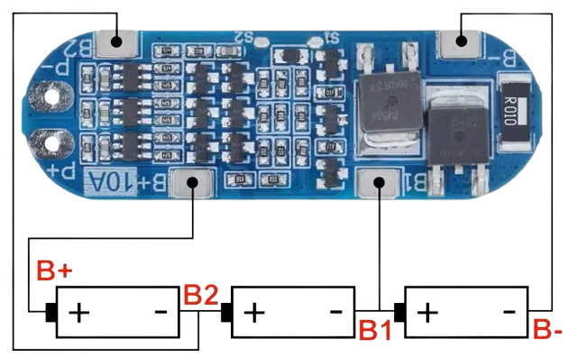
  1. Connect the Battery Pack:

    • Connect the negative terminal of the battery pack to the B- pin.
    • Connect the positive terminal of the first cell to the B1 pin.
    • Connect the positive terminal of the second cell to the B2 pin.
    • Connect the positive terminal of the third cell to the B3 pin.
  2. Connect the Load/Charger:

    • Connect the negative terminal of the load/charger to the P- pin.
    • Connect the positive terminal of the load/charger to the P+ pin.

Important Considerations and Best Practices

  • Ensure Proper Connections: Double-check all connections to avoid short circuits or incorrect wiring.
  • Use Appropriate Wire Gauges: Use wires that can handle the current rating of the BMS to prevent overheating.
  • Monitor Temperature: Ensure the BMS operates within the specified temperature range to avoid damage.
  • Avoid Overloading: Do not exceed the overcurrent protection limit to maintain the safety and longevity of the BMS.

Troubleshooting and FAQs

Common Issues Users Might Face

  1. BMS Not Balancing Cells:

    • Solution: Ensure all cell connections are secure and the cells are within the voltage range for balancing.
  2. Overcurrent Protection Triggering Frequently:

    • Solution: Check for short circuits or reduce the load to stay within the BMS's current rating.
  3. Overcharge/Overdischarge Protection Activating:

    • Solution: Verify the charger and load specifications to ensure they are compatible with the BMS settings.

FAQs

Q1: Can I use the 3S BMS with a different battery configuration?

  • A1: No, the 3S BMS is specifically designed for a 3-cell series configuration. Using it with a different configuration may result in improper operation and potential damage.

Q2: How do I know if the BMS is balancing the cells?

  • A2: You can measure the voltage of each cell. If the voltages are close to each other, the BMS is balancing the cells correctly.

Q3: Can I connect the 3S BMS to an Arduino UNO for monitoring?

  • A3: Yes, you can use an Arduino UNO to monitor the cell voltages and overall battery pack status. Below is an example code snippet for reading cell voltages using an Arduino UNO:
// Example code to read cell voltages using Arduino UNO
// Connect B1, B2, B3 to analog pins A0, A1, A2 respectively

const int cell1Pin = A0; // Pin connected to B1
const int cell2Pin = A1; // Pin connected to B2
const int cell3Pin = A2; // Pin connected to B3

void setup() {
  Serial.begin(9600); // Initialize serial communication
}

void loop() {
  float cell1Voltage = analogRead(cell1Pin) * (5.0 / 1023.0) * 2; // Read and convert voltage
  float cell2Voltage = analogRead(cell2Pin) * (5.0 / 1023.0) * 2; // Read and convert voltage
  float cell3Voltage = analogRead(cell3Pin) * (5.0 / 1023.0) * 2; // Read and convert voltage

  Serial.print("Cell 1 Voltage: ");
  Serial.print(cell1Voltage);
  Serial.println(" V");

  Serial.print("Cell 2 Voltage: ");
  Serial.print(cell2Voltage);
  Serial.println(" V");

  Serial.print("Cell 3 Voltage: ");
  Serial.print(cell3Voltage);
  Serial.println(" V");

  delay(1000); // Wait for 1 second before next reading
}

This code reads the voltages of the three cells and prints them to the serial monitor. Ensure that the voltage divider resistors are used if the cell voltages exceed the Arduino's analog input range.

By following this documentation, users can effectively utilize the 3S BMS in their projects, ensuring safe and efficient battery management.