How to Use optical IR rpm sensor : Examples, Pinouts, and Specs
Introduction
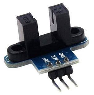
The Youmile Optical IR RPM Sensor is an electronic device designed to measure the rotational speed of an object using infrared light. It operates by emitting an IR beam and detecting the reflection from a rotating object, such as a motor shaft with a reflective marker. This sensor is commonly used in applications like motor speed monitoring, position sensing, and for DIY projects involving rotational speed measurement, such as in robotics or automation systems.
Explore Projects Built with optical IR rpm sensor
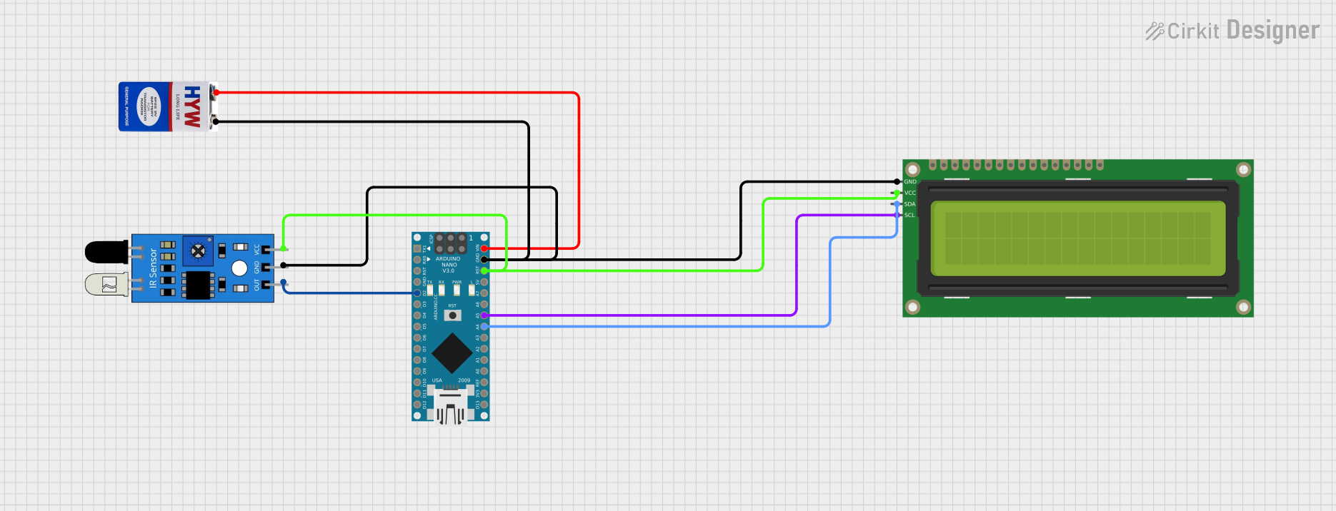
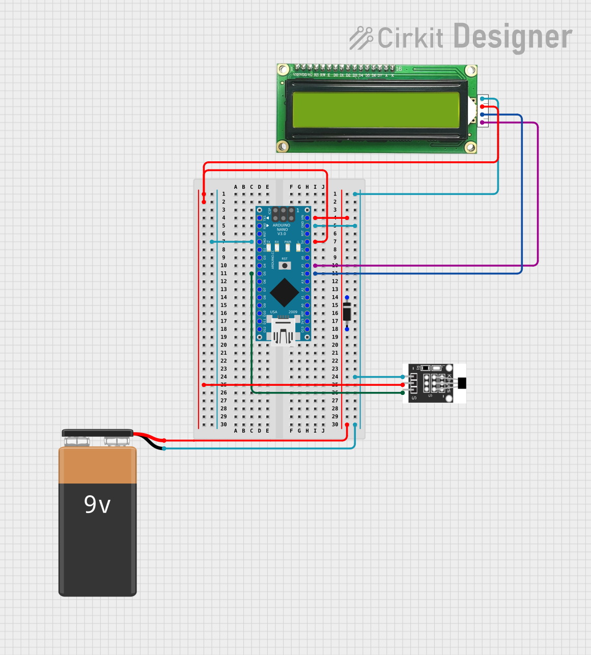
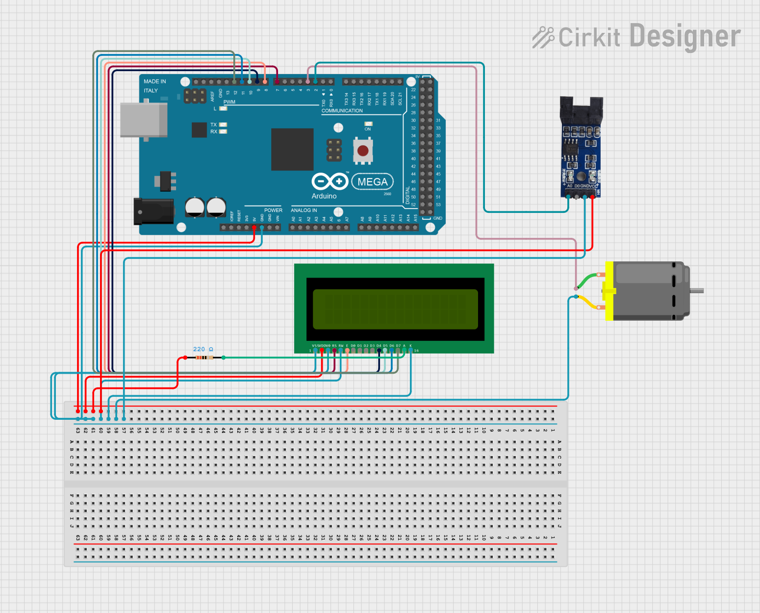
Explore Projects Built with optical IR rpm sensor
Technical Specifications
General Features
- Operating Voltage: 3.3V to 5V
- Output Type: Digital signal
- Sensing Distance: 2-20mm (optimal within 10mm)
- Response Frequency: 100Hz (max)
- Operating Temperature: -25°C to +85°C
Pin Configuration and Descriptions
| Pin Number | Name | Description |
|---|---|---|
| 1 | VCC | Power supply (3.3V to 5V) |
| 2 | GND | Ground connection |
| 3 | DO | Digital output signal |
| 4 | LED | Indicates the presence of an object |
Usage Instructions
Connecting to a Circuit
- Connect the VCC pin to the power supply (3.3V or 5V, depending on your system).
- Connect the GND pin to the ground of your system.
- Connect the DO pin to a digital input pin on your microcontroller, such as an Arduino UNO.
Best Practices
- Ensure that the reflective marker on the rotating object is well-defined and positioned to reflect the IR beam back to the sensor.
- Avoid exposing the sensor to direct sunlight or other strong IR sources, as this may interfere with its operation.
- Keep the sensor at an optimal distance from the reflective surface (2-20mm) for accurate readings.
- Use a debounce algorithm or hardware debouncing to filter out any noise in the digital signal.
Example Arduino Code
// Define the digital pin connected to the sensor's DO pin
const int rpmSensorPin = 2;

void setup() {
  // Initialize the digital pin as an input
  pinMode(rpmSensorPin, INPUT);
  Serial.begin(9600); // Start serial communication at 9600 baud rate
}

void loop() {
  // Read the digital signal from the sensor
  int sensorValue = digitalRead(rpmSensorPin);

  // If a reflection is detected, the output will be LOW
  if (sensorValue == LOW) {
    Serial.println("Reflection detected!");
  } else {
    Serial.println("No reflection detected.");
  }

  // Small delay to prevent overwhelming the serial output
  delay(100);
}
Troubleshooting and FAQs
Common Issues
- Sensor not detecting reflections: Ensure the reflective marker is properly positioned and the sensor is within the optimal sensing distance.
- Inconsistent readings: Check for any potential IR interference and verify that the sensor is not exposed to strong ambient IR light.
- No signal output: Confirm that the sensor is correctly powered and that all connections are secure.
FAQs
Q: Can the sensor be used outdoors? A: While the sensor can operate outdoors, direct sunlight may interfere with its performance. It is recommended to use it in a shaded or controlled environment.
Q: What is the maximum RPM that can be measured? A: The maximum measurable RPM depends on the response frequency of the sensor. With a maximum frequency of 100Hz, the sensor can theoretically measure up to 6000 RPM (100Hz * 60 seconds).
Q: How can I increase the sensing distance? A: The sensing distance is fixed and based on the sensor's design. It is not recommended to modify the sensor to increase the distance, as it may affect its accuracy and reliability.
For further assistance, please refer to the manufacturer's support resources or contact technical support.