How to Use ATmega328: Examples, Pinouts, and Specs
Introduction
The ATmega328 is a low-power 8-bit microcontroller based on the AVR architecture, manufactured by Atmel (now part of Microchip Technology). It is widely used in embedded systems and is particularly popular in Arduino boards, such as the Arduino UNO. The ATmega328 is favored for its ease of use, versatility, and robust performance in controlling various electronic projects, from simple LED blinkers to complex robotics.
Explore Projects Built with ATmega328


Explore Projects Built with ATmega328
Common Applications and Use Cases
- Arduino Projects: The ATmega328 is the heart of many Arduino boards, enabling users to create interactive electronic projects.
- Home Automation: Used in smart home devices for controlling lights, sensors, and appliances.
- Robotics: Ideal for controlling motors, sensors, and other components in robotic systems.
- Wearable Technology: Employed in low-power wearable devices for health monitoring and fitness tracking.
- IoT Devices: Utilized in Internet of Things applications for data collection and device control.
Technical Specifications
Key Technical Details
| Specification | Value |
|---|---|
| Architecture | AVR 8-bit |
| Operating Voltage | 1.8V to 5.5V |
| Maximum Clock Speed | 20 MHz |
| Flash Memory | 32 KB |
| SRAM | 2 KB |
| EEPROM | 1 KB |
| I/O Pins | 23 |
| ADC Channels | 6 (10-bit resolution) |
| PWM Channels | 6 |
| Timer/Counters | 3 |
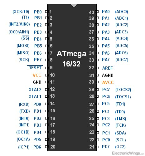
Pin Configuration and Descriptions
| Pin Number | Pin Name | Description |
|---|---|---|
| 1 | PC6 | Reset (active low) |
| 2 | PD0 | Digital I/O, RX (UART) |
| 3 | PD1 | Digital I/O, TX (UART) |
| 4 | PD2 | Digital I/O, External Interrupt 0 |
| 5 | PD3 | Digital I/O, PWM, External Interrupt 1 |
| 6 | PD4 | Digital I/O |
| 7 | VCC | Supply Voltage |
| 8 | GND | Ground |
| 9 | PB0 | Digital I/O, PWM |
| 10 | PB1 | Digital I/O, PWM |
| 11 | PB2 | Digital I/O, PWM |
| 12 | PB3 | Digital I/O, PWM |
| 13 | PB4 | Digital I/O |
| 14 | PB5 | Digital I/O |
| 15 | PC0 | Analog Input 0 |
| 16 | PC1 | Analog Input 1 |
| 17 | PC2 | Analog Input 2 |
| 18 | PC3 | Analog Input 3 |
| 19 | PC4 | Analog Input 4 |
| 20 | PC5 | Analog Input 5 |
Usage Instructions
How to Use the ATmega328 in a Circuit
- Power Supply: Connect the VCC pin to a power source (1.8V to 5.5V) and the GND pin to ground.
- Programming: Use an Arduino board or an external programmer to upload code to the ATmega328.
- I/O Connections: Connect sensors, actuators, and other components to the appropriate I/O pins based on your project requirements.
- Reset Circuit: Include a reset button connected to the RESET pin for easy reprogramming.
Important Considerations and Best Practices
- Voltage Levels: Ensure that the voltage supplied does not exceed 5.5V to avoid damaging the microcontroller.
- Decoupling Capacitors: Use decoupling capacitors (e.g., 0.1 µF) close to the VCC and GND pins to stabilize the power supply.
- Programming: Familiarize yourself with the Arduino IDE for easy programming and debugging.
- Heat Management: Ensure proper heat dissipation if the microcontroller is used in high-power applications.
Troubleshooting and FAQs
Common Issues Users Might Face
Microcontroller Not Responding:
- Check power supply connections and ensure the voltage is within range.
- Verify that the correct board and port are selected in the Arduino IDE.
Code Upload Failure:
- Ensure the correct programmer is selected in the IDE.
- Check the USB connection and try a different USB cable or port.
Unexpected Behavior:
- Review the code for logical errors or incorrect pin assignments.
- Check for short circuits or incorrect wiring in the circuit.
Solutions and Tips for Troubleshooting
- Reset the Microcontroller: Press the reset button before uploading code to ensure it is in the correct state.
- Use Serial Monitor: Utilize the Serial Monitor in the Arduino IDE to debug and view output messages.
- Consult Documentation: Refer to the ATmega328 datasheet for detailed specifications and electrical characteristics.
Example Arduino Code
Here is a simple example of blinking an LED connected to pin 13 of the ATmega328:
// Blink an LED connected to pin 13
void setup() {
  // Set pin 13 as an output
  pinMode(13, OUTPUT);
}

void loop() {
  // Turn the LED on
  digitalWrite(13, HIGH);
  // Wait for 1000 milliseconds (1 second)
  delay(1000);
  // Turn the LED off
  digitalWrite(13, LOW);
  // Wait for 1000 milliseconds (1 second)
  delay(1000);
}
This code initializes pin 13 as an output and toggles the LED on and off every second. It serves as a great starting point for beginners to understand how to control outputs using the ATmega328.