How to Use FS-IA6B: Examples, Pinouts, and Specs
Introduction
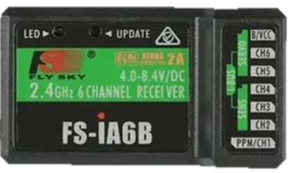
The FS-IA6B is a 6-channel receiver designed for use in remote control applications, particularly in model aircraft. It is part of the FlySky product line and is known for its lightweight design, high sensitivity, and reliable performance. The FS-IA6B supports multiple protocols, making it compatible with a wide range of FlySky transmitters. Its compact size and robust functionality make it an excellent choice for hobbyists and professionals alike.
Explore Projects Built with FS-IA6B


Explore Projects Built with FS-IA6B
Common Applications and Use Cases
- Remote-controlled (RC) airplanes, helicopters, and drones
- RC cars and boats
- Robotics and automation projects requiring wireless control
- Educational projects involving wireless communication
Technical Specifications
The FS-IA6B receiver is designed to provide reliable communication and control in a variety of applications. Below are its key technical details:
| Specification | Details |
|---|---|
| Channels | 6 |
| Operating Voltage Range | 4.0V - 6.5V |
| Signal Output | PWM, iBUS, PPM |
| Frequency Range | 2.405 GHz - 2.475 GHz |
| Modulation Type | GFSK |
| Sensitivity | -105 dBm |
| Antenna | Dual antenna for diversity |
| Dimensions | 47mm x 26.2mm x 15mm |
| Weight | 14.9g |
| Range | Up to 500m (line of sight) |
Pin Configuration and Descriptions
The FS-IA6B features a set of pins for connecting to servos, power, and other devices. Below is the pin configuration:
| Pin | Label | Description |
|---|---|---|
| 1 | CH1 | PWM signal output for Channel 1 |
| 2 | CH2 | PWM signal output for Channel 2 |
| 3 | CH3 | PWM signal output for Channel 3 |
| 4 | CH4 | PWM signal output for Channel 4 |
| 5 | CH5 | PWM signal output for Channel 5 |
| 6 | CH6 | PWM signal output for Channel 6 |
| 7 | B/VCC | Power input (4.0V - 6.5V) |
| 8 | GND | Ground connection |
| 9 | iBUS/PPM | iBUS or PPM signal output for digital communication |
Usage Instructions
The FS-IA6B is straightforward to use and can be integrated into a variety of RC and automation projects. Follow the steps below to use the receiver effectively:
Connecting the FS-IA6B
- Power Supply: Connect the B/VCC pin to a power source within the range of 4.0V to 6.5V. Ensure the GND pin is connected to the ground of the power source.
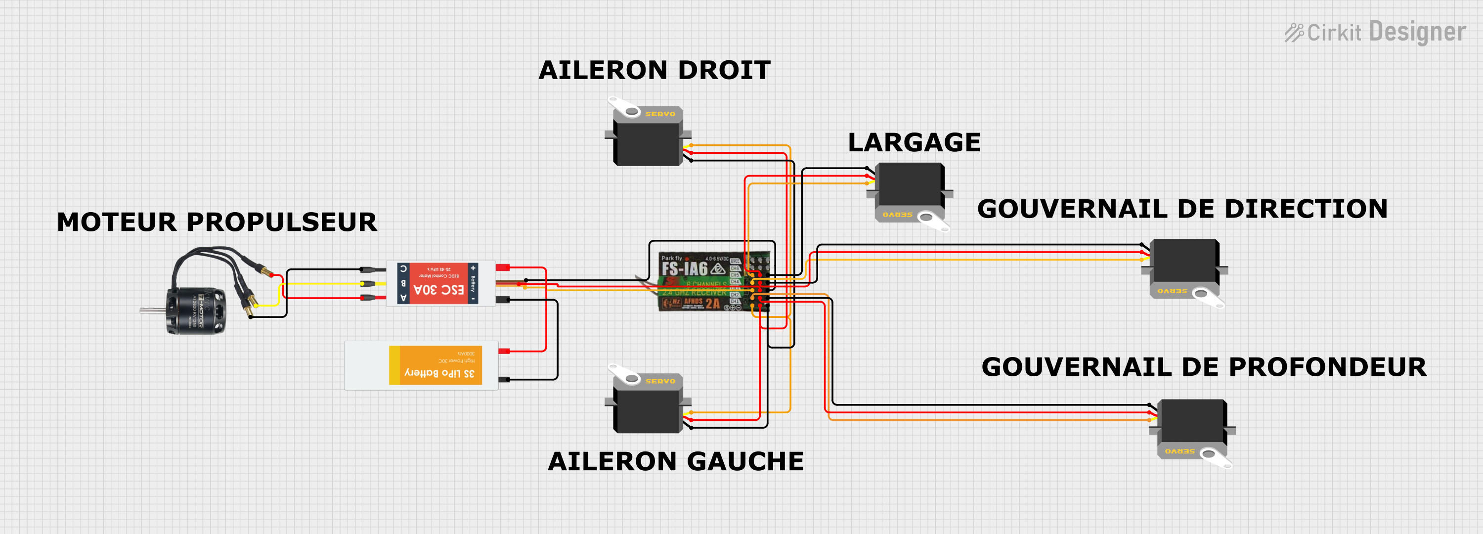
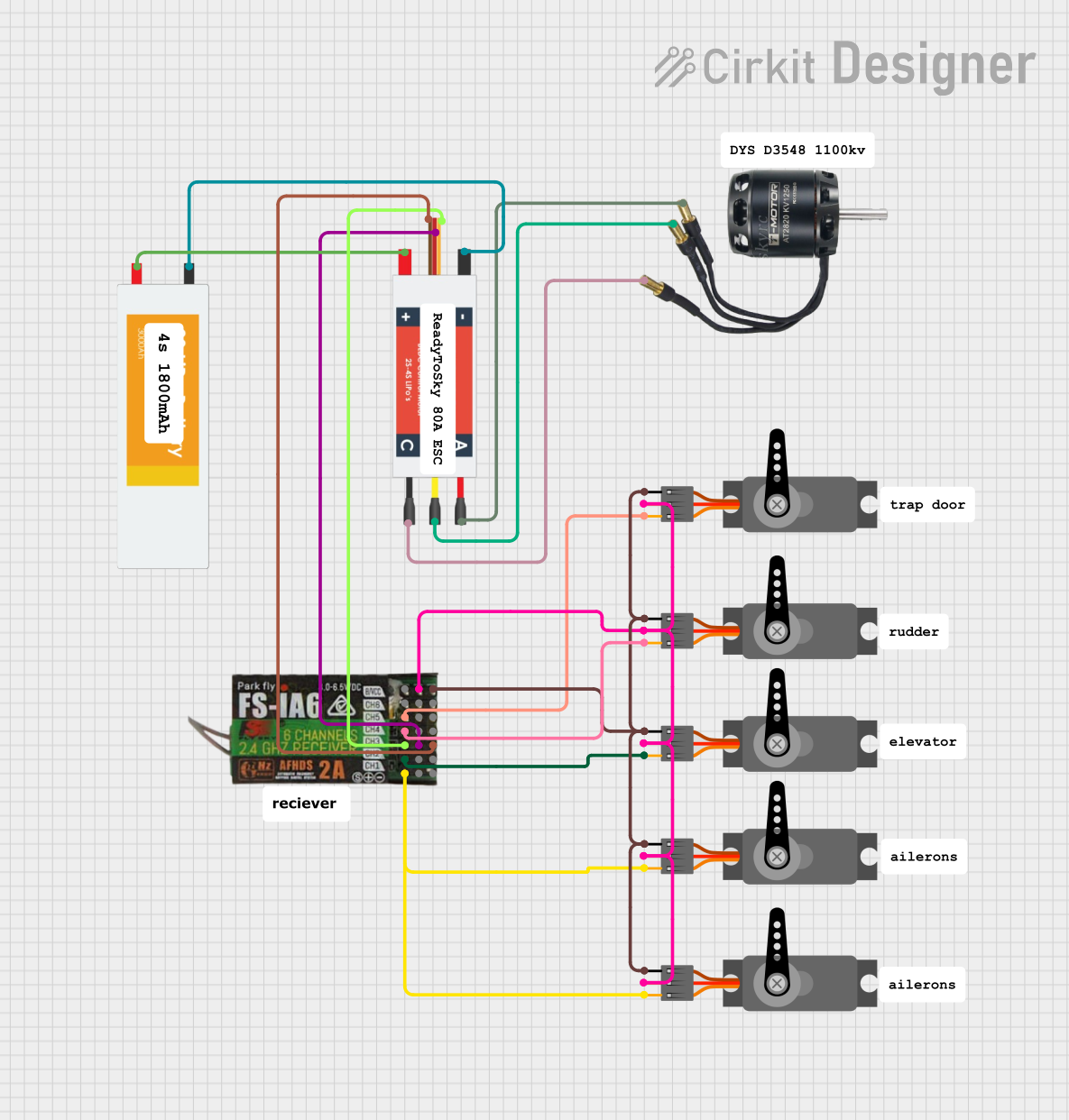
- Servo Connections: Connect your servos or electronic speed controllers (ESCs) to the appropriate channel pins (CH1 to CH6).
- Binding:
- Insert the binding plug into the B/VCC pin.
- Power on the receiver. The LED will start flashing, indicating it is in binding mode.
- Turn on your transmitter in binding mode. Once the LED on the receiver stops flashing and remains solid, the binding process is complete.
- Remove the binding plug and restart the receiver.
Using iBUS or PPM
- For digital communication, connect the iBUS/PPM pin to the corresponding input on your flight controller or microcontroller.
- Configure your transmitter to output iBUS or PPM signals as required.
Example: Connecting to an Arduino UNO
The FS-IA6B can be used with an Arduino UNO for projects requiring wireless control. Below is an example of reading PPM signals from the receiver:
// Example: Reading PPM signals from FS-IA6B using Arduino UNO
// Connect the iBUS/PPM pin of the receiver to Arduino pin 2
// Ensure the receiver is powered within its voltage range

#include <PPMReader.h> // Include a PPM library for decoding signals

#define PPM_PIN 2       // Pin connected to the PPM signal
#define NUM_CHANNELS 6  // Number of channels on the FS-IA6B

PPMReader ppm(PPM_PIN, NUM_CHANNELS);

void setup() {
  Serial.begin(9600); // Initialize serial communication
  Serial.println("FS-IA6B PPM Reader Initialized");
}

void loop() {
  for (int channel = 1; channel <= NUM_CHANNELS; channel++) {
    int value = ppm.latestValidChannelValue(channel, 0);
    // Print the latest value for each channel
    Serial.print("Channel ");
    Serial.print(channel);
    Serial.print(": ");
    Serial.println(value);
  }
  delay(100); // Small delay to avoid flooding the serial monitor
}
Important Considerations and Best Practices
- Antenna Placement: Ensure the dual antennas are positioned at 90 degrees to each other for optimal signal reception.
- Power Supply: Use a stable power source within the specified voltage range to avoid damaging the receiver.
- Range Testing: Perform a range test before using the receiver in critical applications to ensure reliable communication.
- Failsafe Configuration: Configure the failsafe settings on your transmitter to ensure safe operation in case of signal loss.
Troubleshooting and FAQs
Common Issues and Solutions
Receiver Not Binding:
- Ensure the binding plug is correctly inserted into the B/VCC pin.
- Verify that the transmitter is in binding mode and compatible with the FS-IA6B.
- Check the power supply to the receiver.
No Signal Output:
- Confirm that the receiver is bound to the transmitter.
- Verify the connections to the servos or flight controller.
- Ensure the transmitter is configured to output the correct signal type (PWM, iBUS, or PPM).
Short Range or Signal Loss:
- Check the antenna placement and ensure they are not obstructed.
- Avoid operating the receiver near sources of interference, such as Wi-Fi routers.
Receiver LED Flashing:
- A flashing LED indicates the receiver is not bound to a transmitter or has lost the signal. Rebind the receiver if necessary.
FAQs
Q: Can the FS-IA6B be used with non-FlySky transmitters?
A: The FS-IA6B is designed to work with FlySky transmitters using the AFHDS 2A protocol. It is not compatible with other brands unless they support this protocol.
Q: How do I switch between PWM, iBUS, and PPM modes?
A: The signal output mode can be configured through the transmitter settings. Refer to your transmitter's manual for instructions.
Q: What is the maximum range of the FS-IA6B?
A: The receiver has a maximum range of up to 500 meters in line-of-sight conditions.