How to Use ENS161_Evaluation_Kit: Examples, Pinouts, and Specs
Introduction
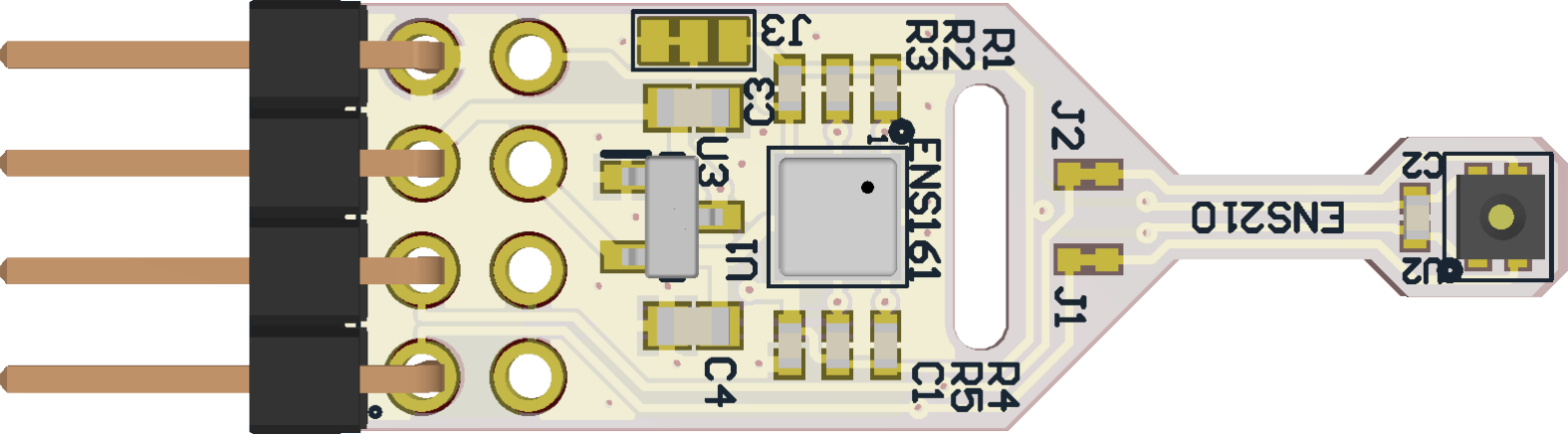
The ENS161 Evaluation Kit (Manufacturer Part ID: ENS161_EvalKit_v3.3) is a development platform created by ScioSense for evaluating and prototyping with the ENS161 sensor. The ENS161 sensor is designed to measure environmental parameters such as temperature and humidity, making it ideal for applications in air quality monitoring, HVAC systems, and IoT-based environmental sensing.
This evaluation kit simplifies the process of testing and integrating the ENS161 sensor into various projects by providing a user-friendly interface and robust connectivity options. It is particularly suited for developers and engineers looking to prototype environmental sensing solutions quickly and efficiently.
Explore Projects Built with ENS161_Evaluation_Kit

Explore Projects Built with ENS161_Evaluation_Kit
Common Applications
- Indoor air quality monitoring
- Smart home and building automation
- HVAC (Heating, Ventilation, and Air Conditioning) systems
- IoT-based environmental sensing
- Industrial and commercial air quality control
Technical Specifications
Key Technical Details
| Parameter | Specification |
|---|---|
| Sensor Type | ENS161 (Temperature and Humidity) |
| Supply Voltage | 3.3V to 5V |
| Communication Interface | I²C |
| Operating Temperature | -40°C to +85°C |
| Humidity Range | 0% to 100% RH (Relative Humidity) |
| Temperature Accuracy | ±0.5°C |
| Humidity Accuracy | ±3% RH |
| Dimensions | Compact PCB design |
Pin Configuration and Descriptions
The ENS161 Evaluation Kit features a standard pin header for easy connection to microcontrollers or other development platforms. Below is the pinout description:
| Pin Number | Pin Name | Description |
|---|---|---|
| 1 | VCC | Power supply input (3.3V to 5V) |
| 2 | GND | Ground |
| 3 | SDA | I²C Data Line |
| 4 | SCL | I²C Clock Line |
| 5 | INT | Interrupt pin (optional, configurable) |
| 6 | NC | Not connected |
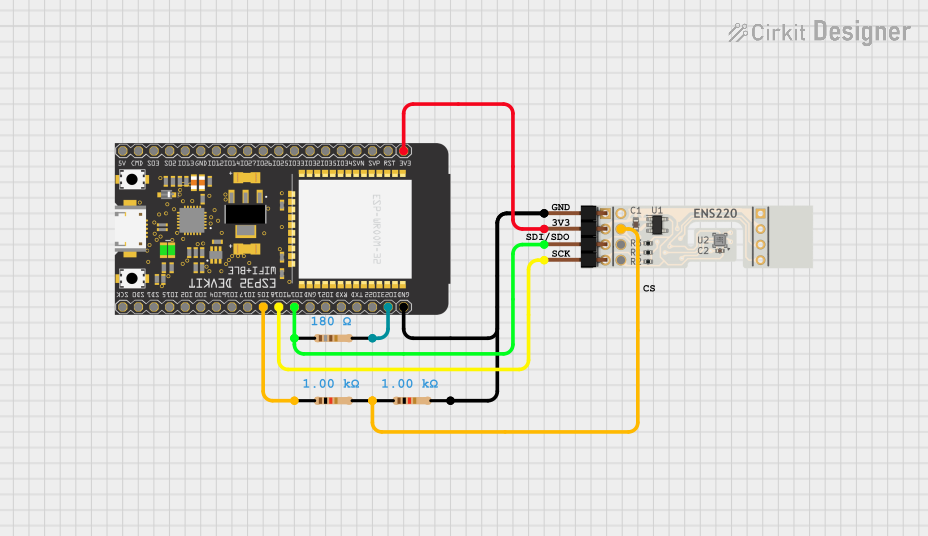
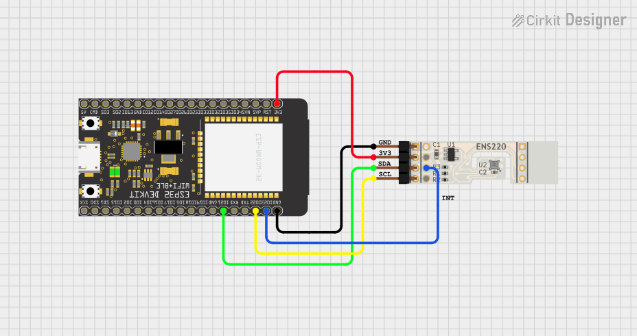
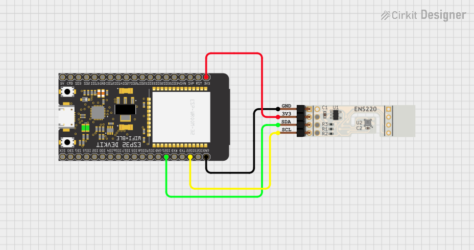
Usage Instructions
How to Use the ENS161 Evaluation Kit in a Circuit
- Power the Kit: Connect the
VCCpin to a 3.3V or 5V power source and theGNDpin to ground. - I²C Communication: Connect the
SDAandSCLpins to the corresponding I²C pins on your microcontroller (e.g., Arduino, Raspberry Pi). - Optional Interrupt: If required, connect the
INTpin to a GPIO pin on your microcontroller to handle interrupts. - Install Libraries: For Arduino users, install the appropriate I²C library or ENS161-specific library (if available).
- Write Code: Use the provided I²C address of the ENS161 sensor to communicate with it and retrieve temperature and humidity data.
Important Considerations and Best Practices
- Ensure the power supply voltage matches the kit's requirements (3.3V to 5V).
- Use pull-up resistors (typically 4.7kΩ) on the
SDAandSCLlines if they are not already included in your setup. - Avoid exposing the sensor to extreme environmental conditions (e.g., condensation, dust) to maintain accuracy.
- Calibrate the sensor if required for your specific application.
Example Code for Arduino UNO
Below is an example Arduino sketch to read temperature and humidity data from the ENS161 Evaluation Kit using the I²C interface:
#include <Wire.h> // Include the Wire library for I²C communication

#define ENS161_I2C_ADDRESS 0x5A // Default I²C address of the ENS161 sensor

void setup() {
  Wire.begin(); // Initialize I²C communication
  Serial.begin(9600); // Start serial communication for debugging

  // Check if the sensor is connected
  Wire.beginTransmission(ENS161_I2C_ADDRESS);
  if (Wire.endTransmission() == 0) {
    Serial.println("ENS161 sensor detected!");
  } else {
    Serial.println("Error: ENS161 sensor not detected. Check connections.");
    while (1); // Halt execution if the sensor is not found
  }
}

void loop() {
  // Request 4 bytes of data from the sensor (example: temperature and humidity)
  Wire.beginTransmission(ENS161_I2C_ADDRESS);
  Wire.write(0x00); // Example register address for data (refer to datasheet)
  Wire.endTransmission();
  Wire.requestFrom(ENS161_I2C_ADDRESS, 4);

  if (Wire.available() == 4) {
    int temp = Wire.read() << 8 | Wire.read(); // Read temperature (2 bytes)
    int hum = Wire.read() << 8 | Wire.read();  // Read humidity (2 bytes)

    // Convert raw data to human-readable values (example conversion)
    float temperature = temp / 100.0; // Assuming data is in hundredths of °C
    float humidity = hum / 100.0;    // Assuming data is in hundredths of %RH

    // Print the results
    Serial.print("Temperature: ");
    Serial.print(temperature);
    Serial.println(" °C");

    Serial.print("Humidity: ");
    Serial.print(humidity);
    Serial.println(" %RH");
  } else {
    Serial.println("Error: Failed to read data from ENS161 sensor.");
  }

  delay(1000); // Wait 1 second before the next reading
}
Troubleshooting and FAQs
Common Issues and Solutions
Sensor Not Detected
- Cause: Incorrect wiring or I²C address mismatch.
- Solution: Double-check the connections and ensure the correct I²C address is used in the code.
Inaccurate Readings
- Cause: Sensor exposed to condensation, dust, or extreme conditions.
- Solution: Ensure the sensor is used in a clean, dry environment. Perform calibration if necessary.
No Data Received
- Cause: Missing pull-up resistors on the I²C lines.
- Solution: Add 4.7kΩ pull-up resistors to the
SDAandSCLlines.
Interrupt Pin Not Working
- Cause: Interrupt functionality not configured in the code.
- Solution: Refer to the ENS161 datasheet for interrupt configuration and ensure the
INTpin is connected to a GPIO pin.
FAQs
Q: Can the ENS161 Evaluation Kit be powered by a 5V Arduino board?
- A: Yes, the kit supports a supply voltage range of 3.3V to 5V.
Q: Is the ENS161 sensor compatible with Raspberry Pi?
- A: Yes, the sensor communicates via I²C, which is supported by Raspberry Pi.
Q: Do I need to calibrate the sensor before use?
- A: The ENS161 sensor is factory-calibrated, but additional calibration may be required for specific applications.
Q: What is the maximum cable length for I²C communication?
- A: The maximum length depends on the pull-up resistor values and communication speed, but it is generally recommended to keep it under 1 meter for reliable operation.
This concludes the documentation for the ENS161 Evaluation Kit. For further details, refer to the official datasheet or contact ScioSense support.