Cirkit Designer Logo
Cirkit Designer
Your all-in-one circuit design IDE
Home / 
Component Documentation

How to Use Regulator Stepdown DC XL4015 CC CV (Biggest): Examples, Pinouts, and Specs

Image of Regulator Stepdown DC XL4015 CC CV (Biggest)
Cirkit Designer LogoDesign with Regulator Stepdown DC XL4015 CC CV (Biggest) in Cirkit Designer

Introduction

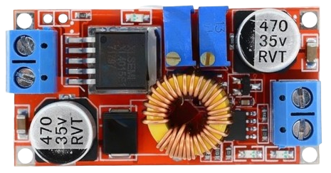
The XL4015 is a buck converter module that steps down DC voltage while maintaining a constant current (CC) and constant voltage (CV). This electronic component is widely used in battery charging, power supplies, LED drivers, and other applications where voltage and current regulation are critical.

Explore Projects Built with Regulator Stepdown DC XL4015 CC CV (Biggest)

Use Cirkit Designer to design, explore, and prototype these projects online. Some projects support real-time simulation. Click "Open Project" to start designing instantly!
Battery-Powered DC Generator with XL4015 Buck Converter
Image of conveyor: A project utilizing Regulator Stepdown DC XL4015 CC CV (Biggest) in a practical application
This circuit consists of a 12V battery connected to a rocker switch, which controls the input to an XL4015 DC Buck Step-down converter. The converter steps down the voltage to power a DC generator, with the generator's output connected back to the converter to form a feedback loop.
Cirkit Designer LogoOpen Project in Cirkit Designer
Battery-Powered Adjustable Voltage Regulator with Li-ion 18650 Batteries and BMS
Image of mini ups: A project utilizing Regulator Stepdown DC XL4015 CC CV (Biggest) in a practical application
This circuit is a power management system that uses four Li-ion 18650 batteries connected to a 2S 30A BMS for battery management and protection. The system includes step-up and step-down voltage regulators to provide adjustable output voltages, controlled by a rocker switch, and multiple DC jacks for power input and output.
Cirkit Designer LogoOpen Project in Cirkit Designer
Smart DC Motor Control System with Relay and Capacitive Sensors
Image of conveyor: A project utilizing Regulator Stepdown DC XL4015 CC CV (Biggest) in a practical application
This circuit controls two DC motors using a combination of relays, a toggle switch, and capacitive sensors. The XL4015 DC Buck Step-down module provides regulated power, while the capacitive sensors and toggle switch are used to control the relays, which in turn manage the operation of the motors.
Cirkit Designer LogoOpen Project in Cirkit Designer
Dual Motor Control Circuit with Directional Switching and Voltage Regulation
Image of Pencuci Kipas: A project utilizing Regulator Stepdown DC XL4015 CC CV (Biggest) in a practical application
This circuit features a 12V battery connected through a rocker switch to two buck converters, one of which steps down the voltage to power two DC mini metal gear motors, and the other is connected to a directional switch that controls a third DC mini metal gear motor. The XL4015 5A DC Buck Step-down converter's output is connected to two motors, allowing them to run at a reduced voltage, while the other buck converter's output is routed through a directional switch to control the direction of the third motor.
Cirkit Designer LogoOpen Project in Cirkit Designer

Explore Projects Built with Regulator Stepdown DC XL4015 CC CV (Biggest)

Use Cirkit Designer to design, explore, and prototype these projects online. Some projects support real-time simulation. Click "Open Project" to start designing instantly!
Image of conveyor: A project utilizing Regulator Stepdown DC XL4015 CC CV (Biggest) in a practical application
Battery-Powered DC Generator with XL4015 Buck Converter
This circuit consists of a 12V battery connected to a rocker switch, which controls the input to an XL4015 DC Buck Step-down converter. The converter steps down the voltage to power a DC generator, with the generator's output connected back to the converter to form a feedback loop.
Cirkit Designer LogoOpen Project in Cirkit Designer
Image of mini ups: A project utilizing Regulator Stepdown DC XL4015 CC CV (Biggest) in a practical application
Battery-Powered Adjustable Voltage Regulator with Li-ion 18650 Batteries and BMS
This circuit is a power management system that uses four Li-ion 18650 batteries connected to a 2S 30A BMS for battery management and protection. The system includes step-up and step-down voltage regulators to provide adjustable output voltages, controlled by a rocker switch, and multiple DC jacks for power input and output.
Cirkit Designer LogoOpen Project in Cirkit Designer
Image of conveyor: A project utilizing Regulator Stepdown DC XL4015 CC CV (Biggest) in a practical application
Smart DC Motor Control System with Relay and Capacitive Sensors
This circuit controls two DC motors using a combination of relays, a toggle switch, and capacitive sensors. The XL4015 DC Buck Step-down module provides regulated power, while the capacitive sensors and toggle switch are used to control the relays, which in turn manage the operation of the motors.
Cirkit Designer LogoOpen Project in Cirkit Designer
Image of Pencuci Kipas: A project utilizing Regulator Stepdown DC XL4015 CC CV (Biggest) in a practical application
Dual Motor Control Circuit with Directional Switching and Voltage Regulation
This circuit features a 12V battery connected through a rocker switch to two buck converters, one of which steps down the voltage to power two DC mini metal gear motors, and the other is connected to a directional switch that controls a third DC mini metal gear motor. The XL4015 5A DC Buck Step-down converter's output is connected to two motors, allowing them to run at a reduced voltage, while the other buck converter's output is routed through a directional switch to control the direction of the third motor.
Cirkit Designer LogoOpen Project in Cirkit Designer

Technical Specifications

Key Technical Details

  • Input Voltage: 4V to 38V DC
  • Output Voltage: 1.25V to 36V DC (adjustable)
  • Output Current: Up to 5A (with proper heat sinking)
  • Maximum Power: 75W (with proper heat sinking)
  • Switching Frequency: 180kHz
  • Efficiency: Up to 96%
  • Operating Temperature: -40°C to +85°C

Pin Configuration and Descriptions

Pin Number Name Description
1 IN+ Input positive
2 IN- Input negative
3 OUT+ Output positive
4 OUT- Output negative
5 CV Constant voltage adjustment
6 CC Constant current adjustment

Usage Instructions

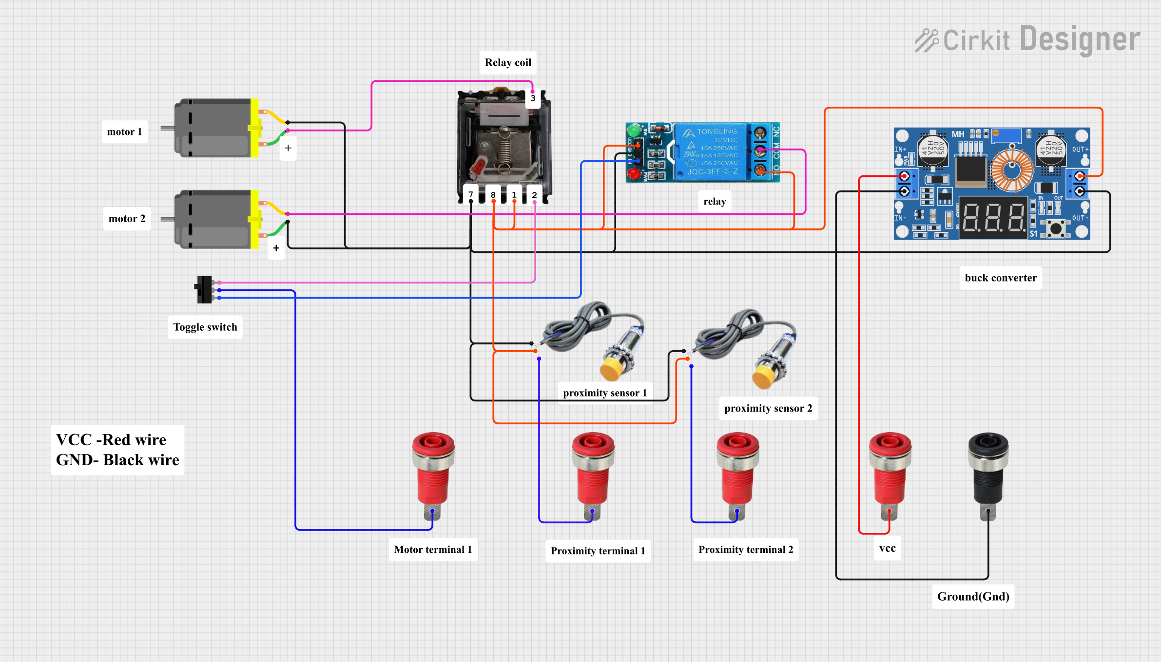
Integration into a Circuit

  1. Connection: Connect the input power supply to the IN+ and IN- pins, ensuring the voltage is within the specified range. Connect the load to the OUT+ and OUT- pins.
  2. Adjustment: Use a multimeter to monitor the output voltage and current. Adjust the CV and CC potentiometers to set the desired output voltage and current limits.
  3. Heat Management: For currents above 2A, or when the module is dissipating significant power, attach a heatsink to the XL4015 chip to prevent overheating.

Best Practices

  • Always verify input voltage before connecting to the module to avoid damage.
  • Start with the CV and CC potentiometers turned fully counterclockwise before powering up.
  • Incrementally adjust the CV and CC settings while monitoring the output to prevent overshooting the desired values.
  • Use a fuse on the input side as a safety precaution against overcurrent conditions.

Troubleshooting and FAQs

Common Issues

  • No Output Voltage: Ensure input power is within the specified range and connections are secure. Check for any short circuits on the output side.
  • Inaccurate Output Voltage or Current: Recalibrate the CV and CC potentiometers. Ensure that the load does not exceed the module's maximum ratings.
  • Overheating: Attach a heatsink to the XL4015 chip and ensure adequate ventilation around the module.

FAQs

Q: Can I use the XL4015 to charge batteries? A: Yes, the XL4015 can be used for battery charging, but ensure to set the CC and CV correctly according to the battery's specifications.

Q: What is the difference between CC and CV modes? A: CC mode limits the output current to a preset level, while CV mode maintains a constant output voltage regardless of changes in load.

Q: How do I know if I need a heatsink? A: If the module is running hot to the touch or if you are running it near the maximum output current for extended periods, a heatsink is recommended.

Example Arduino UNO Connection

// No direct code is used to control the XL4015 with an Arduino UNO
// as it is a standalone module. However, you can monitor the output
// voltage and current using an Arduino if you have the appropriate
// sensors and circuitry to do so safely.

// Always ensure that any connections to the Arduino are within its
// voltage and current specifications to avoid damaging the board.

Remember, the XL4015 is a powerful module that requires careful handling, especially when dealing with high currents and voltages. Always follow safety protocols and consult an expert if you are unsure about your setup.