
How to Use Weigand Keypad: Examples, Pinouts, and Specs
 Design with Weigand Keypad in Cirkit Designer
Introduction
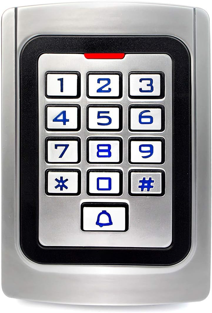
- A Weigand keypad is a security input device commonly used in access control systems. It allows users to enter a numeric code to gain entry to a secured area.
- The keypad communicates with a controller using the Weigand protocol, which transmits data in a binary format. This protocol is widely used in security systems due to its simplicity and reliability.
- Common applications include door access control, time and attendance systems, and secure entry points in residential, commercial, and industrial environments.
Explore Projects Built with Weigand Keypad
 Open Project in Cirkit Designer
 Open Project in Cirkit Designer
 Open Project in Cirkit Designer
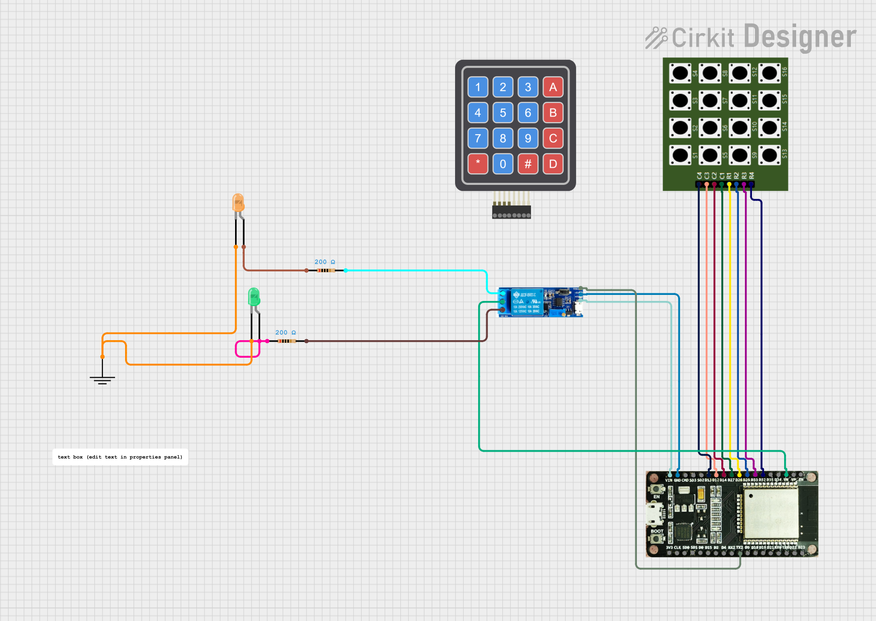 Open Project in Cirkit Designer
Explore Projects Built with Weigand Keypad
Open Project in Cirkit DesignerOpen Project in Cirkit DesignerOpen Project in Cirkit DesignerOpen Project in Cirkit DesignerTechnical Specifications
- Operating Voltage: 5V DC (typical), some models support 12V DC.
- Current Consumption: 30-100 mA (depending on the model and backlight usage).
- Communication Protocol: Weigand (commonly Wiegand-26 or Wiegand-34).
- Keypad Layout: 3x4 or 4x4 matrix (numeric keys 0-9, and optional function keys like
*and#). - Transmission Distance: Up to 150 meters (using shielded twisted-pair cable).
- Operating Temperature: -20°C to 60°C.
- Ingress Protection: Varies by model (e.g., IP65 for outdoor use).
Pin Configuration and Descriptions
Below is a typical pinout for a Weigand keypad. Note that pin configurations may vary slightly depending on the manufacturer.
| Pin Name | Description | Notes |
|---|---|---|
| VCC | Power supply input | Connect to 5V or 12V DC (check model). |
| GND | Ground | Common ground for power and signals. |
| D0 | Data 0 line | Outputs binary data (low signal). |
| D1 | Data 1 line | Outputs binary data (high signal). |
| LED | LED control input | Used to control the keypad's LED. |
| Buzzer | Buzzer control input | Used to control the keypad's buzzer. |
Usage Instructions
Connecting the Weigand Keypad
- Power Supply: Connect the
VCCpin to a 5V or 12V DC power source (depending on the keypad model). Connect theGNDpin to the ground of the power source. - Data Lines: Connect the
D0andD1pins to the corresponding data input pins on the controller or microcontroller. - LED and Buzzer Control: Optionally, connect the
LEDandBuzzerpins to GPIO pins on the controller for feedback control. - Cable Considerations: Use shielded twisted-pair cables for long-distance connections to minimize interference.
Interfacing with an Arduino UNO
Below is an example of how to interface a Weigand keypad with an Arduino UNO. This example assumes the keypad uses the Wiegand-26 protocol.
Circuit Diagram
- Connect
D0to Arduino pin 2. - Connect
D1to Arduino pin 3. - Connect
VCCto the 5V pin on the Arduino. - Connect
GNDto the GND pin on the Arduino.
Sample Code
#include <Wiegand.h> // Include the Wiegand library

WIEGAND wg; // Create a Wiegand object

void setup() {
  Serial.begin(9600); // Initialize serial communication
  wg.begin(2, 3); // Initialize Wiegand on pins 2 (D0) and 3 (D1)
}

void loop() {
  if (wg.available()) {
    // If data is available, read the code and bit length
    Serial.print("Code: ");
    Serial.print(wg.getCode()); // Print the received code
    Serial.print(", Bits: ");
    Serial.println(wg.getWiegandType()); // Print the bit length
  }
}
Important Considerations
- Voltage Compatibility: Ensure the keypad's operating voltage matches your controller's input voltage.
- Cable Length: For long-distance installations, use shielded twisted-pair cables to reduce signal degradation.
- Protocol Support: Verify that your controller or microcontroller supports the Weigand protocol.
- Environmental Protection: If the keypad is installed outdoors, ensure it has an appropriate IP rating (e.g., IP65).
Troubleshooting and FAQs
Common Issues
No Response from the Keypad
- Cause: Incorrect wiring or insufficient power supply.
- Solution: Double-check all connections and ensure the power supply meets the keypad's requirements.
Incorrect or Inconsistent Data
- Cause: Signal interference or incorrect protocol configuration.
- Solution: Use shielded cables and verify that the controller is configured for the correct Weigand protocol (e.g., Wiegand-26 or Wiegand-34).
LED or Buzzer Not Working
- Cause: LED or buzzer control pins not connected or misconfigured.
- Solution: Ensure the
LEDandBuzzerpins are properly connected to GPIO pins on the controller and controlled via software.
FAQs
Q: Can I use a Weigand keypad with a Raspberry Pi?
A: Yes, but you will need to use GPIO pins and a library that supports the Weigand protocol.Q: What is the difference between Wiegand-26 and Wiegand-34?
A: Wiegand-26 uses 26 bits for data transmission, while Wiegand-34 uses 34 bits. The additional bits in Wiegand-34 allow for more unique codes.Q: How do I test if my keypad is working?
A: Connect the keypad to a microcontroller and monitor the data output on the serial monitor. Press keys to verify that the correct codes are transmitted.Q: Can I extend the cable length beyond 150 meters?
A: It is not recommended, as signal degradation may occur. If longer distances are required, consider using signal repeaters or converters.