Cirkit Designer
Your all-in-one circuit design IDE
Home /
Component Documentation
How to Use ESP8266 ESP-02 WiFi Module: Examples, Pinouts, and Specs
Introduction
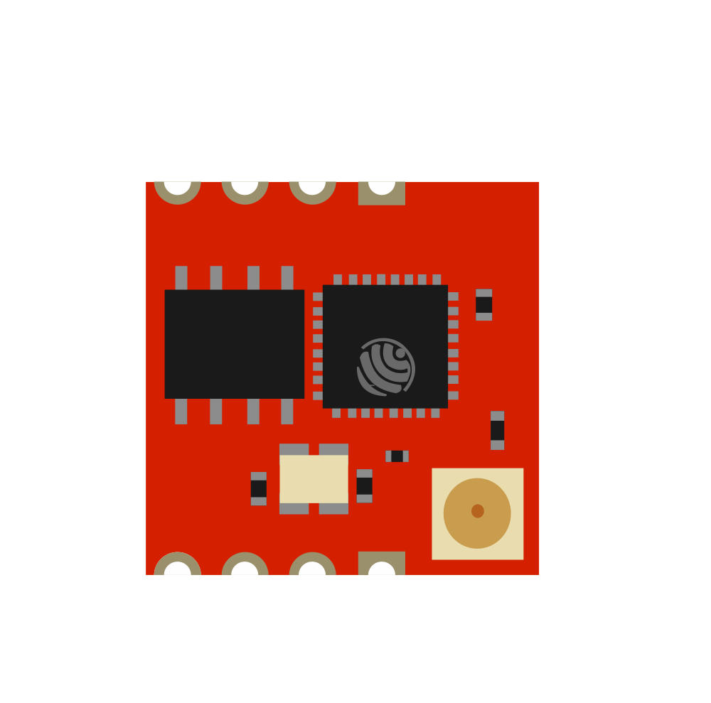
The ESP8266 ESP-02 WiFi Module is a self-contained wireless network controller that can add internet connectivity to your projects. Based on the popular ESP8266 chipset, the ESP-02 variant is known for its small form factor and robust feature set. This module is widely used in the Internet of Things (IoT) applications, home automation systems, and for creating smart devices that can communicate over the internet.
Explore Projects Built with ESP8266 ESP-02 WiFi Module
ESP8266 NodeMCU with LoRa and RS-485 Communication and Ethernet Connectivity

This circuit serves as a multi-protocol communication hub featuring two ESP8266 NodeMCUs for processing, each connected to a LoRa Ra-02 SX1278 for long-range wireless communication. One NodeMCU is also connected to an RS-485 module for serial communication and a W5500 Ethernet module for network connectivity, with MB102 modules supplying power.
ESP8266 NodeMCU with LoRa and RS-485 Communication Interface

This circuit features two ESP8266 NodeMCU microcontrollers, each interfaced with a LoRa Ra-02 SX1278 module for long-range wireless communication, and an RS-485 module for wired serial communication. The ESP8266 microcontrollers are responsible for handling the communication protocols and data processing. Power is supplied to the microcontrollers via an MB102 Breadboard Power Supply Module, which provides both 3.3V and 5V outputs.
ESP8266 and LoRa SX1278 Based Wireless Communication Module

This circuit integrates a LoRa Ra-02 SX1278 module with an ESP8266 NodeMCU to enable long-range wireless communication. The ESP8266 NodeMCU handles the control and data processing, while the LoRa module provides the capability to transmit and receive data over long distances using LoRa technology.
ESP8266 WiFi Module Serial Interface with Pushbutton Control

This circuit features an ESP8266 ESP-01 WiFi module interfaced with an Adafruit FTDI Friend for serial communication. The ESP8266's TXD and RXD pins are connected to the FTDI's RX and TX pins respectively, allowing for data exchange between the microcontroller and a computer. Additionally, a pushbutton is connected to the ESP8266's reset pin, enabling manual resets of the module.
Explore Projects Built with ESP8266 ESP-02 WiFi Module
ESP8266 NodeMCU with LoRa and RS-485 Communication and Ethernet Connectivity
This circuit serves as a multi-protocol communication hub featuring two ESP8266 NodeMCUs for processing, each connected to a LoRa Ra-02 SX1278 for long-range wireless communication. One NodeMCU is also connected to an RS-485 module for serial communication and a W5500 Ethernet module for network connectivity, with MB102 modules supplying power.
ESP8266 NodeMCU with LoRa and RS-485 Communication Interface
This circuit features two ESP8266 NodeMCU microcontrollers, each interfaced with a LoRa Ra-02 SX1278 module for long-range wireless communication, and an RS-485 module for wired serial communication. The ESP8266 microcontrollers are responsible for handling the communication protocols and data processing. Power is supplied to the microcontrollers via an MB102 Breadboard Power Supply Module, which provides both 3.3V and 5V outputs.
ESP8266 and LoRa SX1278 Based Wireless Communication Module
This circuit integrates a LoRa Ra-02 SX1278 module with an ESP8266 NodeMCU to enable long-range wireless communication. The ESP8266 NodeMCU handles the control and data processing, while the LoRa module provides the capability to transmit and receive data over long distances using LoRa technology.
ESP8266 WiFi Module Serial Interface with Pushbutton Control
This circuit features an ESP8266 ESP-01 WiFi module interfaced with an Adafruit FTDI Friend for serial communication. The ESP8266's TXD and RXD pins are connected to the FTDI's RX and TX pins respectively, allowing for data exchange between the microcontroller and a computer. Additionally, a pushbutton is connected to the ESP8266's reset pin, enabling manual resets of the module.
Common Applications and Use Cases
- Smart home devices
- IoT sensors and actuators
- Wireless data logging
- Remote control systems
- Prototyping for WiFi-enabled applications
Technical Specifications
Key Technical Details
- Operating Voltage: 3.0V to 3.6V
- Recommended Operating Voltage: 3.3V
- Operating Current: Average ~80mA
- Wireless Standard: 802.11 b/g/n
- Frequency Range: 2.4 GHz - 2.5 GHz
- Serial/UART baud rate: 115200 bps (default)
Pin Configuration and Descriptions
| Pin Number | Name | Description |
|---|---|---|
| 1 | GND | Ground |
| 2 | GPIO0 | General Purpose Input/Output 0 |
| 3 | GPIO2 | General Purpose Input/Output 2 |
| 4 | RX | UART Receive Pin |
| 5 | TX | UART Transmit Pin |
| 6 | CH_PD | Chip Power-Down Pin |
| 7 | VCC | Power Supply (3.3V) |
Usage Instructions
How to Use the Component in a Circuit
- Power Supply: Connect the VCC pin to a 3.3V power source and the GND pin to the ground.
- Serial Communication: Connect the RX and TX pins to the corresponding TX and RX pins of your microcontroller or USB-to-Serial converter.
- GPIO: The GPIO0 and GPIO2 pins can be used for input or output purposes.
- Programming Mode: To enter programming mode, GPIO0 must be held low during power-up or reset.
- Normal Operation: Ensure CH_PD (Chip Power-Down) is connected to VCC to enable the chip.
Important Considerations and Best Practices
- Do not power the module with more than 3.6V to avoid damaging the device.
- Use a stable power supply capable of delivering sufficient current (up to 300mA during WiFi transmission bursts).
- Ensure proper decoupling with a 100nF capacitor close to the power pins.
- For reliable serial communication, use a baud rate of 115200 bps or configure as needed.
Example Code for Arduino UNO
#include <ESP8266WiFi.h>

// Replace with your network credentials
const char* ssid = "your_SSID";
const char* password = "your_PASSWORD";

void setup() {
  Serial.begin(115200); // Start serial communication at 115200 bps
  WiFi.begin(ssid, password); // Connect to the WiFi network

  while (WiFi.status() != WL_CONNECTED) { // Wait for connection
    delay(500);
    Serial.print(".");
  }

  Serial.println("");
  Serial.println("WiFi connected");
  Serial.println("IP address: ");
  Serial.println(WiFi.localIP()); // Print the local IP address
}

void loop() {
  // Nothing here for this simple example
}
Troubleshooting and FAQs
Common Issues Users Might Face
- Module not responding: Ensure the power supply is stable and within the specified voltage range.
- Cannot connect to WiFi: Verify the SSID and password are correct. Check the signal strength and router settings.
- Serial communication errors: Confirm the baud rate matches between the module and the microcontroller.
Solutions and Tips for Troubleshooting
- Power issues: Use a dedicated 3.3V regulator if the microcontroller's 3.3V pin cannot supply enough current.
- Programming issues: If you cannot upload firmware, check that GPIO0 is grounded during reset to enter programming mode.
- Connection stability: Place a 100nF capacitor close to the power pins to filter out noise and provide a stable power supply.
FAQs
Q: Can I use a 5V power supply with the ESP-02?
- A: No, you must use a 3.3V power supply. Using 5V can damage the module.
Q: How do I reset the module?
- A: Briefly connect the RST pin to GND or power cycle the module.
Q: Can the ESP-02 be used with Arduino IDE?
- A: Yes, you can program the ESP-02 using the Arduino IDE by selecting the appropriate board manager and settings.
Remember to follow all safety precautions when working with electronic components and ensure that all connections are secure before powering up your circuit.