How to Use MCP2551 : Examples, Pinouts, and Specs
Introduction
The MCP2551 is a high-speed CAN (Controller Area Network) transceiver designed to provide a reliable interface between a CAN controller and the physical CAN bus. It supports data rates of up to 1 Mbps and is optimized for low power consumption. This makes it an ideal choice for automotive, industrial, and embedded systems applications where robust communication is required.
Explore Projects Built with MCP2551

Explore Projects Built with MCP2551
Common Applications and Use Cases
- Automotive systems (e.g., engine control units, body control modules)
- Industrial automation and control
- Medical devices
- Embedded systems requiring CAN communication
- Robotics and IoT devices
Technical Specifications
Key Technical Details
- Supply Voltage (Vdd): 4.5V to 5.5V
- Data Rate: Up to 1 Mbps
- Standby Current: 1 µA (typical)
- Bus Voltage Range: -7V to +12V
- Thermal Shutdown Protection: Yes
- ESD Protection: ±4 kV (Human Body Model)
- Operating Temperature Range: -40°C to +125°C
- Package Options: PDIP, SOIC, and others
Pin Configuration and Descriptions
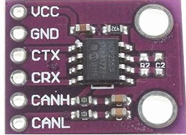
The MCP2551 is an 8-pin IC. Below is the pinout and description:
| Pin Number | Pin Name | Description |
|---|---|---|
| 1 | TXD | Transmit Data Input: Connects to the CAN controller's transmit output. |
| 2 | Vss | Ground: Connect to system ground. |
| 3 | Vdd | Supply Voltage: Connect to a 5V power supply. |
| 4 | RXD | Receive Data Output: Outputs data received from the CAN bus to the controller. |
| 5 | Vref | Reference Voltage Output: Provides a reference voltage (typically 2.5V). |
| 6 | CANL | CAN Low: Connects to the CAN bus low line. |
| 7 | CANH | CAN High: Connects to the CAN bus high line. |
| 8 | RS | Slope Control Input: Adjusts the slew rate for the CAN bus signals. |
Usage Instructions
How to Use the MCP2551 in a Circuit
Power Supply:
- Connect the Vdd pin to a regulated 5V power supply.
- Connect the Vss pin to the system ground.
CAN Bus Connection:
- Connect the CANH and CANL pins to the corresponding lines of the CAN bus.
- Use a 120-ohm termination resistor between CANH and CANL at each end of the bus.
Controller Interface:
- Connect the TXD pin to the CAN controller's transmit output.
- Connect the RXD pin to the CAN controller's receive input.
Slope Control:
- Connect the RS pin to ground for high-speed operation.
- For reduced EMI, connect a resistor between RS and ground to control the slew rate.
Reference Voltage:
- The Vref pin provides a 2.5V reference voltage, which can be used for external circuits if needed.
Important Considerations and Best Practices
- Ensure proper termination of the CAN bus with 120-ohm resistors at both ends to avoid signal reflections.
- Keep the CANH and CANL lines as short and twisted as possible to minimize noise and interference.
- Avoid connecting the MCP2551 directly to a 3.3V CAN controller. Use a level shifter or ensure the controller is 5V tolerant.
- Use decoupling capacitors (e.g., 0.1 µF) close to the Vdd pin to stabilize the power supply.
Example: Connecting MCP2551 to an Arduino UNO
Below is an example of how to connect the MCP2551 to an Arduino UNO for CAN communication:
Circuit Connections
- MCP2551 TXD → Arduino Digital Pin 10
- MCP2551 RXD → Arduino Digital Pin 11
- MCP2551 Vdd → Arduino 5V
- MCP2551 Vss → Arduino GND
- MCP2551 CANH → CAN Bus High Line
- MCP2551 CANL → CAN Bus Low Line
- MCP2551 RS → GND (for high-speed mode)
Arduino Code Example
#include <SPI.h>
#include <mcp2515.h> // Include the MCP2515 CAN library

struct can_frame canMsg; // Define a CAN message structure
MCP2515 mcp2515(10);     // Initialize MCP2515 with CS pin 10

void setup() {
  Serial.begin(9600); // Start serial communication for debugging
  if (mcp2515.begin(MCP_ANY) != CAN_OK) {
    Serial.println("MCP2515 Initialization Failed!");
    while (1);
  }
  Serial.println("MCP2515 Initialized Successfully!");

  mcp2515.setBitrate(CAN_500KBPS, MCP_8MHZ); // Set CAN bitrate to 500 kbps
  mcp2515.setNormalMode(); // Set MCP2515 to normal mode
}

void loop() {
  // Example: Sending a CAN message
  canMsg.can_id = 0x100; // Set CAN ID
  canMsg.can_dlc = 2;    // Set data length (2 bytes)
  canMsg.data[0] = 0x55; // First byte of data
  canMsg.data[1] = 0xAA; // Second byte of data

  if (mcp2515.sendMessage(&canMsg) == CAN_OK) {
    Serial.println("Message Sent Successfully!");
  } else {
    Serial.println("Error Sending Message!");
  }

  delay(1000); // Wait 1 second before sending the next message
}
Troubleshooting and FAQs
Common Issues and Solutions
MCP2551 Not Responding:
- Cause: Incorrect wiring or power supply issues.
- Solution: Double-check all connections, especially Vdd, Vss, TXD, and RXD.
No Data on CAN Bus:
- Cause: Missing or incorrect termination resistors.
- Solution: Ensure 120-ohm resistors are present at both ends of the CAN bus.
High Noise or EMI:
- Cause: Improper RS pin configuration.
- Solution: Use a resistor on the RS pin to control the slew rate.
Communication Errors:
- Cause: Mismatched CAN bitrates between devices.
- Solution: Verify that all devices on the CAN bus are configured with the same bitrate.
FAQs
Q: Can the MCP2551 work with a 3.3V CAN controller?
A: The MCP2551 requires a 5V supply. Use a level shifter or ensure the controller is 5V tolerant.Q: What is the maximum cable length for the CAN bus?
A: The maximum length depends on the data rate. For 1 Mbps, the recommended maximum is 40 meters.Q: Can I use the MCP2551 in low-power applications?
A: Yes, the MCP2551 has a low standby current of 1 µA, making it suitable for low-power designs.