How to Use Estardyn TFT 160 x 80 Display: Examples, Pinouts, and Specs
Introduction
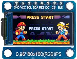
The Estardyn TFT 160 x 80 Display is a compact thin-film transistor (TFT) display module with a resolution of 160 x 80 pixels. It is designed for use in embedded systems and projects requiring a small, vibrant display for graphics and text. This display is ideal for applications such as IoT devices, handheld gadgets, and user interfaces for microcontroller-based systems. Its small size and low power consumption make it a popular choice for portable and battery-powered projects.
Explore Projects Built with Estardyn TFT 160 x 80 Display


Explore Projects Built with Estardyn TFT 160 x 80 Display
Technical Specifications
- Display Type: TFT (Thin-Film Transistor)
- Resolution: 160 x 80 pixels
- Screen Size: 0.96 inches (diagonal)
- Interface: SPI (Serial Peripheral Interface)
- Operating Voltage: 3.3V (logic level)
- Backlight Voltage: 3.0V to 3.3V
- Current Consumption: ~15mA (typical, with backlight on)
- Driver IC: ST7735
- Color Depth: 65K colors (16-bit RGB)
- Viewing Angle: ~160 degrees
- Operating Temperature: -20°C to 70°C
Pin Configuration and Descriptions
The Estardyn TFT 160 x 80 Display typically has an 8-pin interface. Below is the pinout and description:
| Pin | Name | Description |
|---|---|---|
| 1 | GND | Ground connection. Connect to the ground of the power supply. |
| 2 | VCC | Power supply input (3.3V). |
| 3 | SCL (CLK) | SPI clock line. Used for synchronizing data transfer. |
| 4 | SDA (MOSI) | SPI data line (Master Out Slave In). Transfers data from the microcontroller. |
| 5 | RES | Reset pin. Active low. Resets the display module. |
| 6 | DC (A0) | Data/Command pin. High for data, low for command. |
| 7 | CS | Chip Select. Active low. Enables communication with the display. |
| 8 | BLK | Backlight control. Connect to 3.3V for constant backlight or PWM for dimming. |
Usage Instructions
Connecting the Display to a Microcontroller
To use the Estardyn TFT 160 x 80 Display, connect it to a microcontroller such as an Arduino UNO. Below is a typical wiring guide:
| Display Pin | Arduino UNO Pin |
|---|---|
| GND | GND |
| VCC | 3.3V |
| SCL (CLK) | D13 (SCK) |
| SDA (MOSI) | D11 (MOSI) |
| RES | D8 |
| DC (A0) | D9 |
| CS | D10 |
| BLK | 3.3V or PWM pin |
Example Code for Arduino UNO
The following example demonstrates how to initialize and display basic graphics on the Estardyn TFT 160 x 80 Display using the Adafruit GFX and Adafruit ST7735 libraries.
#include <Adafruit_GFX.h>    // Core graphics library
#include <Adafruit_ST7735.h> // Hardware-specific library for ST7735

// Define pins for the display
#define TFT_CS   10  // Chip Select pin
#define TFT_RST   8  // Reset pin
#define TFT_DC    9  // Data/Command pin

// Initialize the display object
Adafruit_ST7735 tft = Adafruit_ST7735(TFT_CS, TFT_DC, TFT_RST);

void setup() {
  // Initialize the display
  tft.initR(INITR_MINI160x80); // Initialize for 160x80 resolution
  tft.setRotation(1);         // Set display orientation (1 = landscape)

  // Fill the screen with a color
  tft.fillScreen(ST77XX_BLACK);

  // Display text
  tft.setTextColor(ST77XX_WHITE);
  tft.setTextSize(1);
  tft.setCursor(10, 10);
  tft.print("Hello, World!");

  // Draw a rectangle
  tft.drawRect(20, 20, 50, 30, ST77XX_RED);
}

void loop() {
  // Nothing to do here
}
Important Considerations
- Voltage Levels: Ensure the logic level of your microcontroller matches the display's 3.3V requirement. Use a level shifter if your microcontroller operates at 5V.
- Backlight Control: For adjustable brightness, connect the BLK pin to a PWM-capable pin on your microcontroller.
- Library Compatibility: Use the Adafruit GFX and Adafruit ST7735 libraries for easy integration and access to graphics functions.
- SPI Speed: Ensure the SPI clock speed is within the display's supported range (typically up to 15 MHz).
Troubleshooting and FAQs
Common Issues
Blank Screen:
- Verify all connections are secure and correct.
- Ensure the display is powered with 3.3V and not 5V.
- Check if the reset (RES) pin is properly connected.
Distorted or Noisy Display:
- Reduce the SPI clock speed in your microcontroller code.
- Ensure proper grounding between the display and the microcontroller.
Backlight Not Turning On:
- Confirm the BLK pin is connected to 3.3V or a PWM pin.
- Check the current supply to ensure it meets the backlight's requirements.
Library Errors:
- Ensure the Adafruit GFX and Adafruit ST7735 libraries are installed in your Arduino IDE.
- Verify that the correct initialization function (
initR(INITR_MINI160x80)) is used.
FAQs
Q: Can I use this display with a 5V microcontroller?
A: Yes, but you must use a logic level shifter to convert the 5V signals to 3.3V for the display.
Q: How do I control the brightness of the backlight?
A: Connect the BLK pin to a PWM-capable pin on your microcontroller and use analogWrite() to adjust brightness.
Q: Can I use this display with platforms other than Arduino?
A: Yes, the display can be used with other platforms like Raspberry Pi, ESP32, or STM32, provided they support SPI communication.
Q: What is the maximum SPI clock speed supported by the display?
A: The display typically supports SPI clock speeds up to 15 MHz. Check the driver IC datasheet for exact details.