How to Use MKS Servo42C NEMA 17 Stepper motor: Examples, Pinouts, and Specs
Introduction
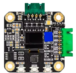
The MKS Servo42C NEMA 17 Stepper Motor, manufactured by Makerbase (Part ID: 42C), is a high-torque stepper motor designed for applications requiring precise control and high-resolution positioning. With its NEMA 17 frame size, it is compact yet powerful, making it ideal for robotics, CNC machines, 3D printers, and other motion control systems. This motor integrates closed-loop control for enhanced accuracy and efficiency, reducing missed steps and improving overall performance.
Explore Projects Built with MKS Servo42C NEMA 17 Stepper motor
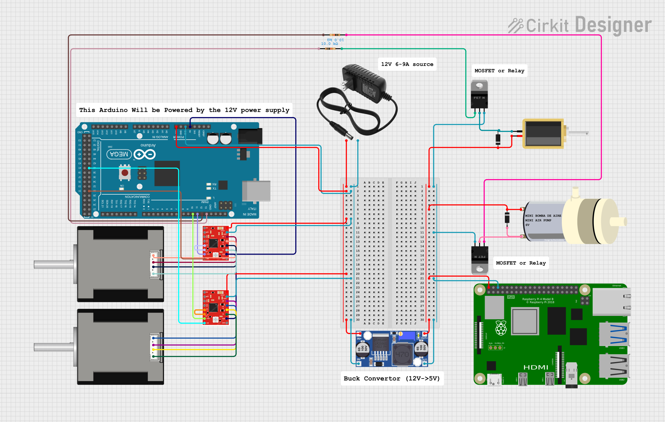

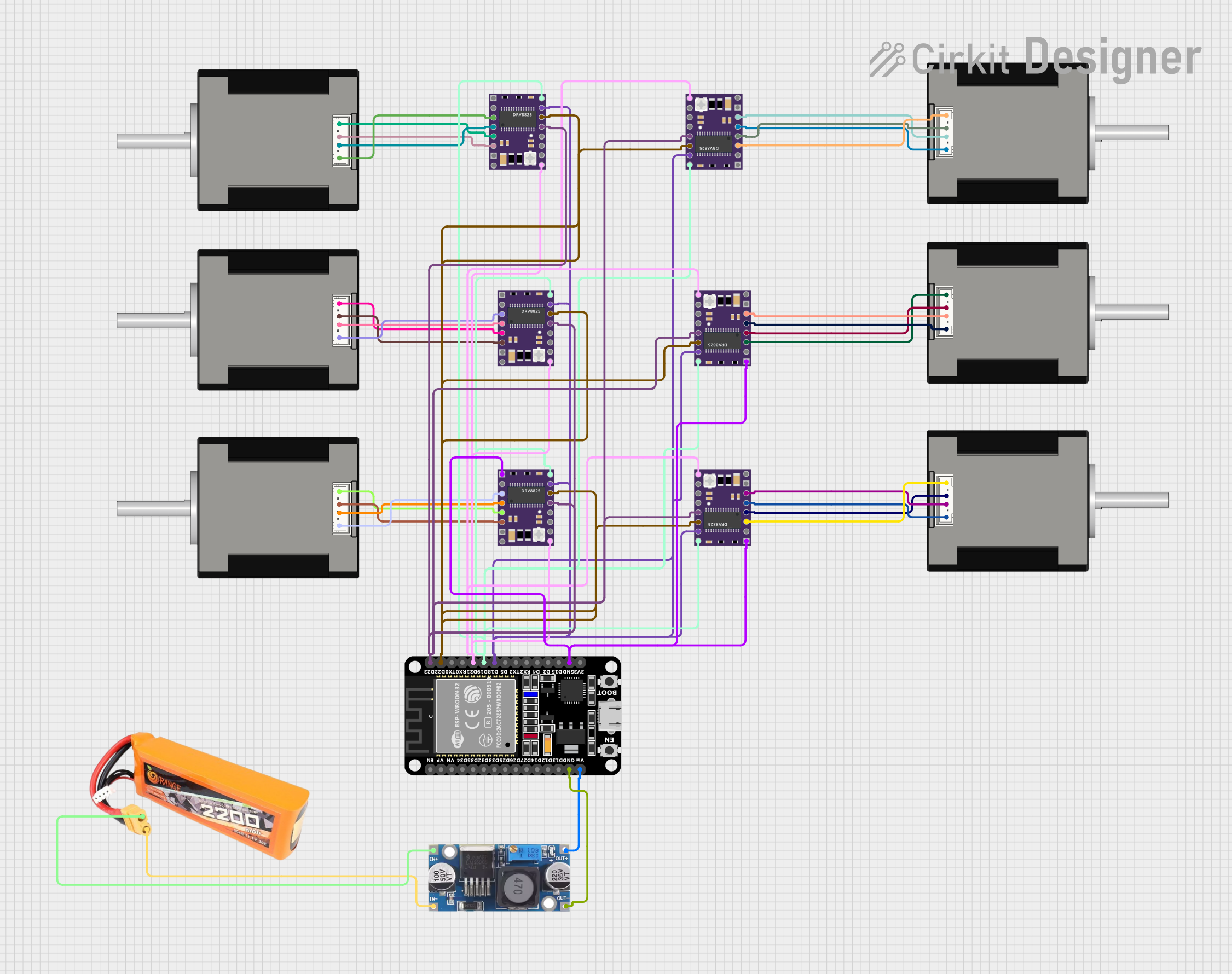
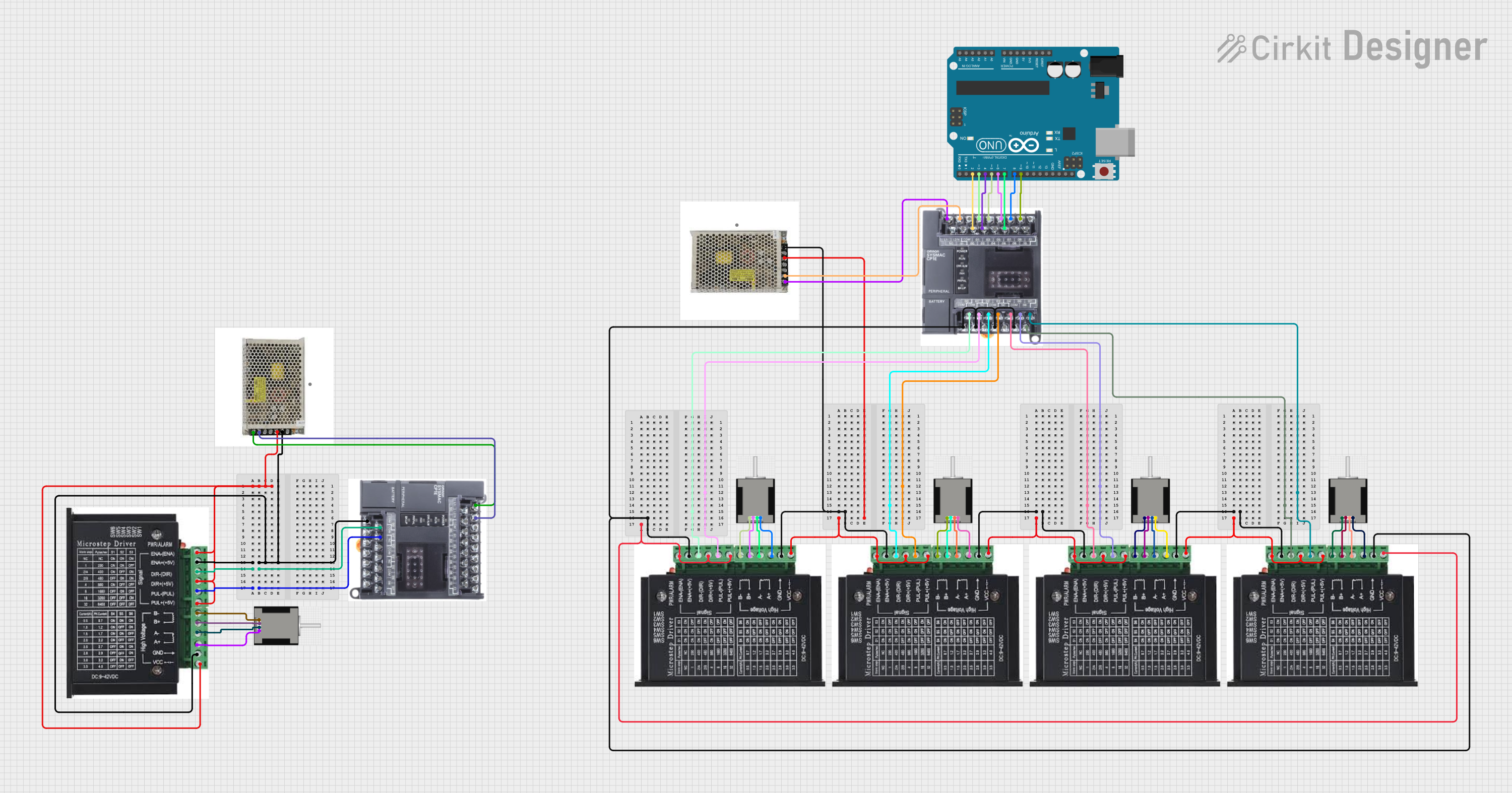
Explore Projects Built with MKS Servo42C NEMA 17 Stepper motor
Common Applications
- 3D printers for precise layer positioning
- CNC machines for accurate cutting and engraving
- Robotics for controlled motion and positioning
- Automated conveyor systems
- Camera sliders and gimbals
Technical Specifications
Key Technical Details
| Parameter | Value |
|---|---|
| Frame Size | NEMA 17 (42mm x 42mm) |
| Step Angle | 1.8° |
| Holding Torque | Up to 0.5 Nm (varies by model) |
| Rated Voltage | 12V |
| Rated Current | 1.5A per phase |
| Resistance per Phase | 2.4Ω |
| Inductance per Phase | 3.2mH |
| Encoder Resolution | 1000 pulses per revolution |
| Communication Interface | UART |
| Operating Temperature | -10°C to 50°C |
| Weight | ~300g |
Pin Configuration and Descriptions
The MKS Servo42C features a standard 4-pin connector for motor phases and additional pins for encoder and control signals.
Motor Phase Pins
| Pin Number | Label | Description |
|---|---|---|
| 1 | A+ | Phase A positive terminal |
| 2 | A- | Phase A negative terminal |
| 3 | B+ | Phase B positive terminal |
| 4 | B- | Phase B negative terminal |
Encoder and Control Pins
| Pin Number | Label | Description |
|---|---|---|
| 1 | VCC | Power supply for encoder (5V) |
| 2 | GND | Ground |
| 3 | TX | UART transmit signal |
| 4 | RX | UART receive signal |
Usage Instructions
How to Use the Component in a Circuit
- Power Supply: Ensure the motor is powered with a 12V DC supply capable of delivering sufficient current (at least 1.5A per phase).
- Connection: Connect the motor phase pins (A+, A-, B+, B-) to a compatible stepper motor driver. For closed-loop operation, connect the encoder pins (VCC, GND, TX, RX) to the control board.
- Control Signals: Use a microcontroller (e.g., Arduino UNO) or a dedicated CNC controller to send step and direction signals to the motor driver.
- Programming: Configure the motor driver or microcontroller to match the motor's step angle and current rating.
Important Considerations and Best Practices
- Current Limiting: Set the motor driver's current limit to 1.5A to prevent overheating or damage.
- Cooling: Ensure adequate ventilation or heat dissipation for prolonged operation.
- Wiring: Double-check all connections to avoid short circuits or incorrect wiring.
- Encoder Calibration: If using closed-loop control, calibrate the encoder for accurate feedback.
- Power Supply: Use a stable and noise-free power supply to avoid erratic motor behavior.
Example Code for Arduino UNO
Below is an example of how to control the MKS Servo42C using an Arduino UNO and a stepper motor driver.
// Include the Stepper library for controlling the motor
#include <Stepper.h>

// Define the number of steps per revolution for the motor
#define STEPS_PER_REV 200  // 1.8° step angle = 200 steps per revolution

// Initialize the Stepper object with the motor's step pins
Stepper stepper(STEPS_PER_REV, 8, 9, 10, 11);
// Pins 8, 9, 10, 11 are connected to the motor driver

void setup() {
  // Set the motor speed in RPM
  stepper.setSpeed(60);  // 60 RPM
  Serial.begin(9600);    // Initialize serial communication for debugging
  Serial.println("Stepper motor test initialized.");
}

void loop() {
  // Rotate the motor 1 revolution clockwise
  Serial.println("Rotating clockwise...");
  stepper.step(STEPS_PER_REV);

  delay(1000);  // Wait for 1 second

  // Rotate the motor 1 revolution counterclockwise
  Serial.println("Rotating counterclockwise...");
  stepper.step(-STEPS_PER_REV);

  delay(1000);  // Wait for 1 second
}
Notes on the Code
- Adjust the
STEPS_PER_REVvalue if the motor's step angle differs from 1.8°. - Ensure the motor driver is compatible with the Arduino's output voltage (5V logic).
Troubleshooting and FAQs
Common Issues and Solutions
Motor Not Moving
- Cause: Incorrect wiring or insufficient power supply.
- Solution: Verify all connections and ensure the power supply meets the motor's requirements.
Overheating
- Cause: Current limit set too high or inadequate cooling.
- Solution: Reduce the current limit on the motor driver and improve ventilation.
Erratic Movement
- Cause: Electrical noise or incorrect step signal timing.
- Solution: Use shielded cables and ensure proper grounding. Adjust the step pulse timing in the controller.
Missed Steps
- Cause: Excessive load or incorrect microstepping settings.
- Solution: Reduce the load or adjust the microstepping configuration.
FAQs
Can I use the MKS Servo42C with a 24V power supply? No, the motor is rated for 12V operation. Using a higher voltage may damage the motor or driver.
What is the advantage of the built-in encoder? The encoder provides closed-loop feedback, ensuring precise positioning and reducing the risk of missed steps.
Is the motor compatible with GRBL-based CNC controllers? Yes, the motor can be used with GRBL controllers as long as the driver supports step and direction signals.
How do I calibrate the encoder? Refer to the manufacturer's documentation or software tools for encoder calibration procedures.
This concludes the documentation for the MKS Servo42C NEMA 17 Stepper Motor. For further assistance, consult the Makerbase support team or community forums.