Cirkit Designer Logo
Cirkit Designer
Your all-in-one circuit design IDE
Home / 
Component Documentation

How to Use GX12-6PIN: Examples, Pinouts, and Specs

Image of GX12-6PIN
Cirkit Designer LogoDesign with GX12-6PIN in Cirkit Designer

Introduction

The GX12-6PIN is a circular electrical connector with six pins, designed for secure and reliable connections in electronic systems. Its robust construction and compact design make it ideal for applications requiring both power and signal transmission. The GX12-6PIN is widely used in industrial equipment, robotics, audio systems, and DIY electronics projects.

Explore Projects Built with GX12-6PIN

Use Cirkit Designer to design, explore, and prototype these projects online. Some projects support real-time simulation. Click "Open Project" to start designing instantly!
KRYPTON-6xSTG Signal Processing Circuit
Image of Industrijski seminar: A project utilizing GX12-6PIN in a practical application
The circuit consists of two KRYPTON-6xSTG components connected in series, where the 'OUT' pin of the first component is connected to the 'IN' pin of the second component. This setup suggests a signal or data flow from the first KRYPTON-6xSTG to the second.
Cirkit Designer LogoOpen Project in Cirkit Designer
Dual 5V Power Supply Distribution Circuit with Toggle Switch Control
Image of rfdriver: A project utilizing GX12-6PIN in a practical application
This circuit consists of two 5V 5A power supplies connected to an AC wall plug point, providing DC output through a 12-way connector. The ground connections from both power supplies are interconnected and also connected to the ground pins of two toggle switches. The DC outputs from the power supplies are separately connected to different pins on the 12-way connector, with each power supply output being switchable via one of the toggle switches.
Cirkit Designer LogoOpen Project in Cirkit Designer
Satellite-Based Timing and Navigation System with SDR and Atomic Clock Synchronization
Image of GPS 시스템 측정 구성도_Confirm: A project utilizing GX12-6PIN in a practical application
This circuit appears to be a complex system involving power supply management, GPS and timing synchronization, and data communication. It includes a SI-TEX G1 Satellite Compass for GPS data, an XHTF1021 Atomic Rubidium Clock for precise timing, and Ettus USRP B200 units for software-defined radio communication. Power is supplied through various SMPS units and distributed via terminal blocks and DC jacks. Data communication is facilitated by Beelink MINI S12 N95 computers, RS232 splitters, and a 1000BASE-T Media Converter for network connectivity. RF Directional Couplers are used to interface antennas with the USRP units, and the entire system is likely contained within cases for protection and organization.
Cirkit Designer LogoOpen Project in Cirkit Designer
24V Pushbutton Control Interface with 40-Pin Connector
Image of 4 på rad: A project utilizing GX12-6PIN in a practical application
This circuit consists of a 24V power supply unit (PSU) connected to four pushbuttons. Each pushbutton is wired such that pressing it will send a 24V signal to a corresponding general-purpose input (GP In) on a 40-pin connector. The common return path for the pushbuttons is connected to the 0V of the PSU, which is also connected to the common (Com) for input pins on the 40-pin connector, completing the circuit for each button press.
Cirkit Designer LogoOpen Project in Cirkit Designer

Explore Projects Built with GX12-6PIN

Use Cirkit Designer to design, explore, and prototype these projects online. Some projects support real-time simulation. Click "Open Project" to start designing instantly!
Image of Industrijski seminar: A project utilizing GX12-6PIN in a practical application
KRYPTON-6xSTG Signal Processing Circuit
The circuit consists of two KRYPTON-6xSTG components connected in series, where the 'OUT' pin of the first component is connected to the 'IN' pin of the second component. This setup suggests a signal or data flow from the first KRYPTON-6xSTG to the second.
Cirkit Designer LogoOpen Project in Cirkit Designer
Image of rfdriver: A project utilizing GX12-6PIN in a practical application
Dual 5V Power Supply Distribution Circuit with Toggle Switch Control
This circuit consists of two 5V 5A power supplies connected to an AC wall plug point, providing DC output through a 12-way connector. The ground connections from both power supplies are interconnected and also connected to the ground pins of two toggle switches. The DC outputs from the power supplies are separately connected to different pins on the 12-way connector, with each power supply output being switchable via one of the toggle switches.
Cirkit Designer LogoOpen Project in Cirkit Designer
Image of GPS 시스템 측정 구성도_Confirm: A project utilizing GX12-6PIN in a practical application
Satellite-Based Timing and Navigation System with SDR and Atomic Clock Synchronization
This circuit appears to be a complex system involving power supply management, GPS and timing synchronization, and data communication. It includes a SI-TEX G1 Satellite Compass for GPS data, an XHTF1021 Atomic Rubidium Clock for precise timing, and Ettus USRP B200 units for software-defined radio communication. Power is supplied through various SMPS units and distributed via terminal blocks and DC jacks. Data communication is facilitated by Beelink MINI S12 N95 computers, RS232 splitters, and a 1000BASE-T Media Converter for network connectivity. RF Directional Couplers are used to interface antennas with the USRP units, and the entire system is likely contained within cases for protection and organization.
Cirkit Designer LogoOpen Project in Cirkit Designer
Image of 4 på rad: A project utilizing GX12-6PIN in a practical application
24V Pushbutton Control Interface with 40-Pin Connector
This circuit consists of a 24V power supply unit (PSU) connected to four pushbuttons. Each pushbutton is wired such that pressing it will send a 24V signal to a corresponding general-purpose input (GP In) on a 40-pin connector. The common return path for the pushbuttons is connected to the 0V of the PSU, which is also connected to the common (Com) for input pins on the 40-pin connector, completing the circuit for each button press.
Cirkit Designer LogoOpen Project in Cirkit Designer

Common Applications

  • Industrial machinery and automation systems
  • Robotics and motor control
  • Audio and video equipment
  • DIY electronics and prototyping
  • Power and signal transmission in embedded systems

Technical Specifications

Key Technical Details

Parameter Specification
Manufacturer GX12-6PIN
Part ID GX12-6PIN
Number of Pins 6
Connector Type Circular
Rated Voltage 250V AC/DC
Rated Current 5A
Contact Resistance ≤ 5 mΩ
Insulation Resistance ≥ 1000 MΩ
Operating Temperature -50°C to +85°C
Material (Shell) Zinc alloy with nickel plating
Material (Contacts) Brass with silver plating
Mounting Style Panel mount or cable mount
Locking Mechanism Threaded coupling

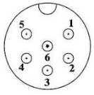
Pin Configuration and Descriptions

The GX12-6PIN connector has six pins arranged in a circular pattern. Below is the pinout description:

Pin Number Description Typical Use Case
1 Signal/Power Line 1 Positive voltage or signal
2 Signal/Power Line 2 Negative voltage or signal
3 Signal/Power Line 3 Ground or common connection
4 Signal/Power Line 4 Auxiliary signal or power line
5 Signal/Power Line 5 Auxiliary signal or power line
6 Signal/Power Line 6 Auxiliary signal or power line

Usage Instructions

How to Use the GX12-6PIN in a Circuit

  1. Connector Assembly:

    • For cable mounting, solder the wires to the corresponding pins on the connector.
    • Ensure proper insulation to avoid short circuits between pins.
    • Use the threaded coupling to securely connect the male and female parts of the connector.
  2. Panel Mounting:

    • Drill a hole in the panel to fit the connector's diameter (12mm).
    • Secure the connector using the provided nut and washer.
  3. Wiring:

    • Identify the pin numbers on the connector (usually marked on the back).
    • Match the pins to the corresponding signals or power lines in your circuit.
  4. Testing:

    • After assembly, test the connections using a multimeter to ensure continuity and proper wiring.

Important Considerations and Best Practices

  • Voltage and Current Ratings: Do not exceed the rated voltage (250V) or current (5A) to avoid damage or overheating.
  • Environmental Conditions: Ensure the connector is used within the specified temperature range (-50°C to +85°C).
  • Secure Connections: Always tighten the threaded coupling to prevent accidental disconnection.
  • Polarity: Double-check the polarity of power lines to avoid reverse connections.

Example: Connecting to an Arduino UNO

The GX12-6PIN can be used to connect external sensors or devices to an Arduino UNO. Below is an example of wiring and code for reading a sensor signal:

Wiring

  • Pin 1: Connect to Arduino 5V
  • Pin 2: Connect to Arduino GND
  • Pin 3: Connect to Arduino Analog Pin A0 (sensor signal)
  • Pins 4-6: Not used in this example

Arduino Code

// Example code for reading a sensor signal via GX12-6PIN connector
const int sensorPin = A0; // Pin A0 connected to GX12-6PIN Pin 3
int sensorValue = 0;      // Variable to store sensor reading

void setup() {
  Serial.begin(9600); // Initialize serial communication at 9600 baud
  pinMode(sensorPin, INPUT); // Set sensor pin as input
}

void loop() {
  sensorValue = analogRead(sensorPin); // Read the sensor value
  Serial.print("Sensor Value: ");      // Print the sensor value to the serial monitor
  Serial.println(sensorValue);
  delay(500); // Wait for 500ms before the next reading
}

Troubleshooting and FAQs

Common Issues and Solutions

  1. Loose Connections:

    • Issue: The connector feels loose or disconnects easily.
    • Solution: Ensure the threaded coupling is tightened securely.
  2. No Signal or Power:

    • Issue: The connected device does not receive power or signal.
    • Solution: Check the wiring and ensure the correct pins are connected. Use a multimeter to verify continuity.
  3. Overheating:

    • Issue: The connector becomes hot during operation.
    • Solution: Ensure the current does not exceed the 5A rating. Check for short circuits.
  4. Corrosion or Damage:

    • Issue: The connector shows signs of corrosion or physical damage.
    • Solution: Replace the connector and ensure it is used in a suitable environment.

FAQs

Q1: Can the GX12-6PIN be used outdoors?
A1: The GX12-6PIN is not inherently waterproof. For outdoor use, ensure it is housed in a weatherproof enclosure.

Q2: What tools are needed for assembly?
A2: You will need a soldering iron, wire stripper, and a wrench for securing the panel mount.

Q3: Can I use all six pins for power lines?
A3: Yes, but ensure the total current does not exceed the 5A rating.

Q4: Is the GX12-6PIN compatible with other GX connectors?
A4: The GX12-6PIN is only compatible with other GX12-6PIN connectors. It will not mate with GX16 or GX20 connectors.