Cirkit Designer Logo
Cirkit Designer
Your all-in-one circuit design IDE
Home / 
Component Documentation

How to Use STM32G431CoreBoard: Examples, Pinouts, and Specs

Image of STM32G431CoreBoard
Cirkit Designer LogoDesign with STM32G431CoreBoard in Cirkit Designer

Introduction

The STM32G431CoreBoard by WeActStudio is a compact and versatile development board built around the STM32G431 microcontroller. This microcontroller features an ARM Cortex-M4 core with high performance, low power consumption, and a rich set of peripherals, making it ideal for a wide range of embedded applications. The board is designed to simplify prototyping and development for engineers, hobbyists, and students.

Explore Projects Built with STM32G431CoreBoard

Use Cirkit Designer to design, explore, and prototype these projects online. Some projects support real-time simulation. Click "Open Project" to start designing instantly!
Solar-Powered STM32-Based Automation System with Matrix Keypad and RTC
Image of soloar cleaner : A project utilizing STM32G431CoreBoard in a practical application
This circuit features an STM32F103C8T6 microcontroller interfaced with a membrane matrix keypad for input, an RTC DS3231 for real-time clock functionality, and a 16x2 I2C LCD for display. It controls four 12V geared motors through two MD20 CYTRON motor drivers, with the motor power supplied by a 12V battery regulated by a buck converter. The battery is charged via a solar panel connected through a solar charge controller, ensuring a renewable energy source for the system.
Cirkit Designer LogoOpen Project in Cirkit Designer
STM32F4-Based Multi-Sensor GPS Tracking System
Image of Phase 1 fc: A project utilizing STM32G431CoreBoard in a practical application
This circuit integrates an STM32F4 microcontroller with a GPS module (NEO 6M), an accelerometer and gyroscope (MPU-6050), a barometric pressure sensor (BMP280), and a compass (HMC5883L). The microcontroller communicates with the sensors via I2C and the GPS module via UART, enabling it to gather and process environmental and positional data.
Cirkit Designer LogoOpen Project in Cirkit Designer
STM32F103C8T6 Bluetooth-Controlled Arcade Joystick Interface
Image of RC카 조이스틱: A project utilizing STM32G431CoreBoard in a practical application
This circuit features an STM32F103C8T6 microcontroller interfaced with a Bluetooth HC-06 module for wireless communication and an Adafruit Arcade Joystick for user input. The microcontroller's pins B0 and B10 are connected to the TXD and RXD pins of the Bluetooth module, enabling serial communication, while pins B14 and B15 interface with the joystick's directional controls. The circuit is powered by a battery, with power distribution managed through the microcontroller's 3.3V pin and common ground connections.
Cirkit Designer LogoOpen Project in Cirkit Designer
STM32F103C8T6-Based Water Level Monitoring and Communication System with SIM900A and LoRa Connectivity
Image of water level: A project utilizing STM32G431CoreBoard in a practical application
This circuit features a microcontroller (STM32F103C8T6) interfaced with a SIM900A GSM module, an HC-SR04 ultrasonic sensor, a water level sensor, and a LoRa Ra-02 SX1278 module for long-range communication. The STM32F103C8T6 is configured to communicate with the GSM module and LoRa module via serial connections, and it reads data from the ultrasonic and water level sensors. An FTDI Programmer is connected for programming and serial communication with the microcontroller.
Cirkit Designer LogoOpen Project in Cirkit Designer

Explore Projects Built with STM32G431CoreBoard

Use Cirkit Designer to design, explore, and prototype these projects online. Some projects support real-time simulation. Click "Open Project" to start designing instantly!
Image of soloar cleaner : A project utilizing STM32G431CoreBoard in a practical application
Solar-Powered STM32-Based Automation System with Matrix Keypad and RTC
This circuit features an STM32F103C8T6 microcontroller interfaced with a membrane matrix keypad for input, an RTC DS3231 for real-time clock functionality, and a 16x2 I2C LCD for display. It controls four 12V geared motors through two MD20 CYTRON motor drivers, with the motor power supplied by a 12V battery regulated by a buck converter. The battery is charged via a solar panel connected through a solar charge controller, ensuring a renewable energy source for the system.
Cirkit Designer LogoOpen Project in Cirkit Designer
Image of Phase 1 fc: A project utilizing STM32G431CoreBoard in a practical application
STM32F4-Based Multi-Sensor GPS Tracking System
This circuit integrates an STM32F4 microcontroller with a GPS module (NEO 6M), an accelerometer and gyroscope (MPU-6050), a barometric pressure sensor (BMP280), and a compass (HMC5883L). The microcontroller communicates with the sensors via I2C and the GPS module via UART, enabling it to gather and process environmental and positional data.
Cirkit Designer LogoOpen Project in Cirkit Designer
Image of RC카 조이스틱: A project utilizing STM32G431CoreBoard in a practical application
STM32F103C8T6 Bluetooth-Controlled Arcade Joystick Interface
This circuit features an STM32F103C8T6 microcontroller interfaced with a Bluetooth HC-06 module for wireless communication and an Adafruit Arcade Joystick for user input. The microcontroller's pins B0 and B10 are connected to the TXD and RXD pins of the Bluetooth module, enabling serial communication, while pins B14 and B15 interface with the joystick's directional controls. The circuit is powered by a battery, with power distribution managed through the microcontroller's 3.3V pin and common ground connections.
Cirkit Designer LogoOpen Project in Cirkit Designer
Image of water level: A project utilizing STM32G431CoreBoard in a practical application
STM32F103C8T6-Based Water Level Monitoring and Communication System with SIM900A and LoRa Connectivity
This circuit features a microcontroller (STM32F103C8T6) interfaced with a SIM900A GSM module, an HC-SR04 ultrasonic sensor, a water level sensor, and a LoRa Ra-02 SX1278 module for long-range communication. The STM32F103C8T6 is configured to communicate with the GSM module and LoRa module via serial connections, and it reads data from the ultrasonic and water level sensors. An FTDI Programmer is connected for programming and serial communication with the microcontroller.
Cirkit Designer LogoOpen Project in Cirkit Designer

Common Applications

  • Motor control and industrial automation
  • IoT devices and smart home systems
  • Signal processing and audio applications
  • Robotics and drones
  • General-purpose embedded systems

Technical Specifications

Key Technical Details

Parameter Specification
Microcontroller STM32G431 (ARM Cortex-M4, 32-bit)
Operating Voltage 3.3V
Input Voltage Range 5V (via USB) or 3.3V (via external power supply)
Clock Speed Up to 170 MHz
Flash Memory 128 KB
SRAM 32 KB
Communication Interfaces UART, I2C, SPI, CAN, USB
GPIO Pins 30+
ADC Resolution 12-bit (up to 16 channels)
PWM Channels 6
Debug Interface SWD (Serial Wire Debug)
Dimensions 50mm x 20mm

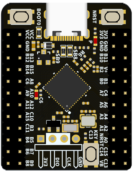
Pin Configuration and Descriptions

The STM32G431CoreBoard features a dual-row pin header layout. Below is the pinout description:

Pin Number Pin Name Functionality
1 3.3V Power supply (3.3V output)
2 GND Ground
3 PA0 GPIO/ADC_IN0
4 PA1 GPIO/ADC_IN1
5 PA2 GPIO/UART2_TX
6 PA3 GPIO/UART2_RX
7 PB6 GPIO/I2C1_SCL
8 PB7 GPIO/I2C1_SDA
9 PC13 GPIO/User Button
10 NRST Reset Pin
11 SWDIO Debug Interface (SWDIO)
12 SWCLK Debug Interface (SWCLK)

Note: Refer to the official datasheet for a complete pinout and alternate functions.

Usage Instructions

How to Use the STM32G431CoreBoard in a Circuit

  1. Powering the Board:

    • Connect the board to a 5V USB power source or supply 3.3V directly to the 3.3V pin.
    • Ensure the ground (GND) is connected to the power supply's ground.
  2. Programming the Board:

    • Use an ST-Link programmer or USB-to-serial adapter to upload firmware.
    • Alternatively, use the USB interface for programming via STM32CubeProgrammer.
  3. Connecting Peripherals:

    • Use GPIO pins for digital input/output.
    • Connect sensors or analog devices to ADC pins (e.g., PA0, PA1).
    • Use UART, I2C, or SPI pins for communication with external modules.
  4. Debugging:

    • Connect an SWD debugger to the SWDIO and SWCLK pins for real-time debugging.

Important Considerations and Best Practices

  • Voltage Levels: Ensure all connected peripherals operate at 3.3V logic levels to avoid damage.
  • Decoupling Capacitors: Add decoupling capacitors near power pins for stable operation.
  • Pin Protection: Avoid leaving unused pins floating; configure them as input with pull-up/down resistors.
  • Heat Management: If running at high clock speeds, ensure adequate ventilation to prevent overheating.

Example: Blinking an LED with Arduino IDE

The STM32G431CoreBoard can be programmed using the Arduino IDE with the STM32 core installed. Below is an example of blinking an LED connected to pin PA0.

// Example: Blink an LED connected to PA0
// Ensure the STM32 core is installed in Arduino IDE

#define LED_PIN PA0  // Define the pin connected to the LED

void setup() {
  pinMode(LED_PIN, OUTPUT);  // Set PA0 as an output pin
}

void loop() {
  digitalWrite(LED_PIN, HIGH);  // Turn the LED on
  delay(500);                   // Wait for 500 milliseconds
  digitalWrite(LED_PIN, LOW);   // Turn the LED off
  delay(500);                   // Wait for 500 milliseconds
}

Tip: Install the STM32 core for Arduino IDE from the Boards Manager to enable support for STM32G431.

Troubleshooting and FAQs

Common Issues and Solutions

  1. Board Not Detected by Programmer:

    • Ensure the board is powered correctly.
    • Check the connection between the programmer and the SWD pins.
    • Verify that the correct board and port are selected in the programming software.
  2. Program Upload Fails:

    • Check for proper drivers installed for the ST-Link or USB interface.
    • Ensure the board is in bootloader mode if using USB for programming.
  3. Peripherals Not Working:

    • Double-check the pin connections and configurations in the code.
    • Verify that the peripheral's voltage and current requirements are met.
  4. Board Overheating:

    • Reduce the clock speed if running at maximum frequency.
    • Check for short circuits or excessive current draw from connected peripherals.

FAQs

Q: Can I power the board directly from a LiPo battery?
A: Yes, but ensure the battery voltage is regulated to 3.3V before connecting to the 3.3V pin.

Q: Does the board support USB communication?
A: Yes, the STM32G431CoreBoard supports USB communication for programming and data transfer.

Q: How do I reset the board?
A: Press the onboard reset button or pull the NRST pin low momentarily.

Q: Can I use the board for motor control?
A: Absolutely! The STM32G431 features advanced motor control peripherals, making it suitable for such applications.

For additional support, refer to the official WeActStudio documentation or community forums.