
How to Use LCD 20X4: Examples, Pinouts, and Specs
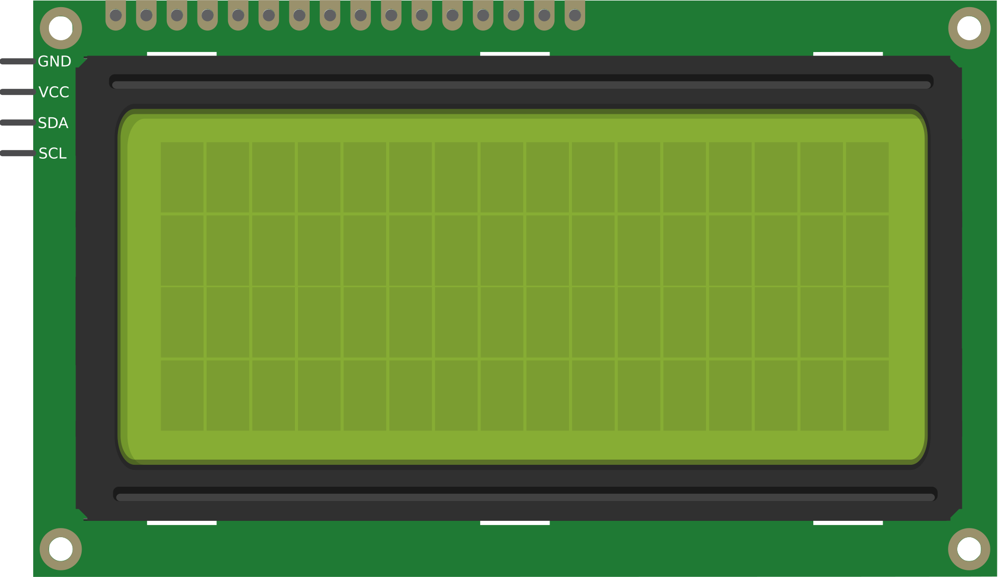
 Design with LCD 20X4 in Cirkit Designer
Introduction
The LCD 20x4 is a Liquid Crystal Display capable of displaying 20 characters per line across 4 lines. It is widely used in embedded systems and microcontroller projects for presenting textual information such as sensor readings, system status, or user instructions. This display module is based on the HD44780 controller, making it compatible with most microcontrollers, including Arduino, Raspberry Pi, and other development boards.
Explore Projects Built with LCD 20X4
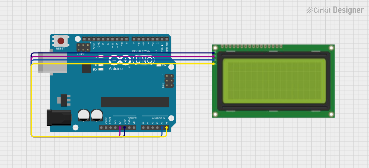 Open Project in Cirkit Designer
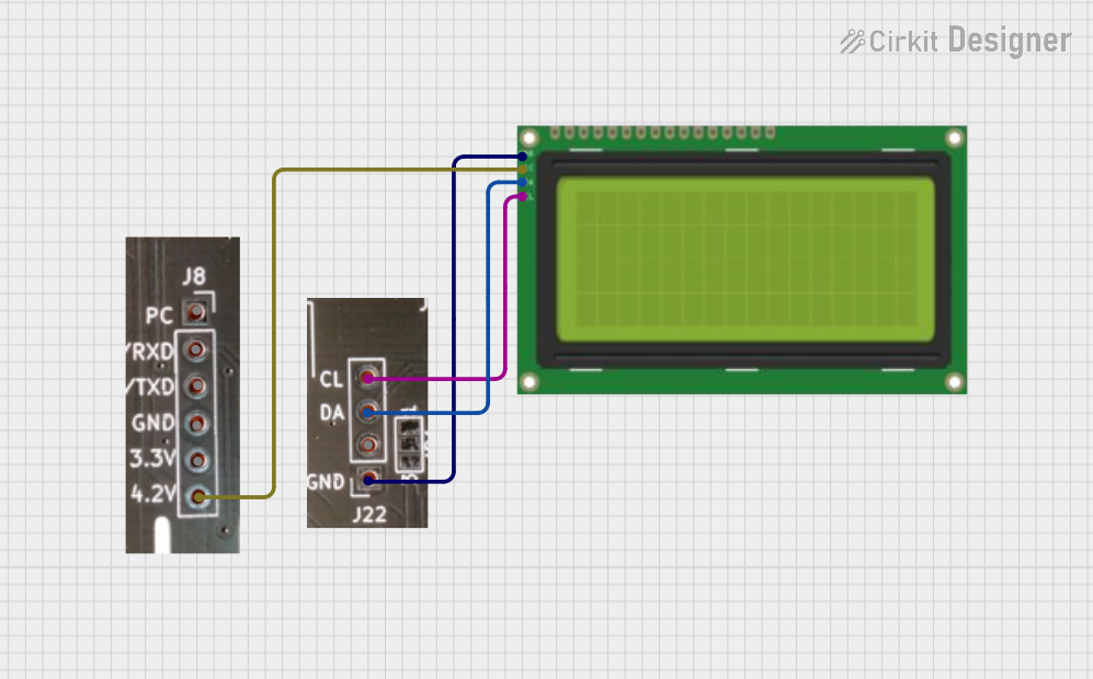 Open Project in Cirkit Designer
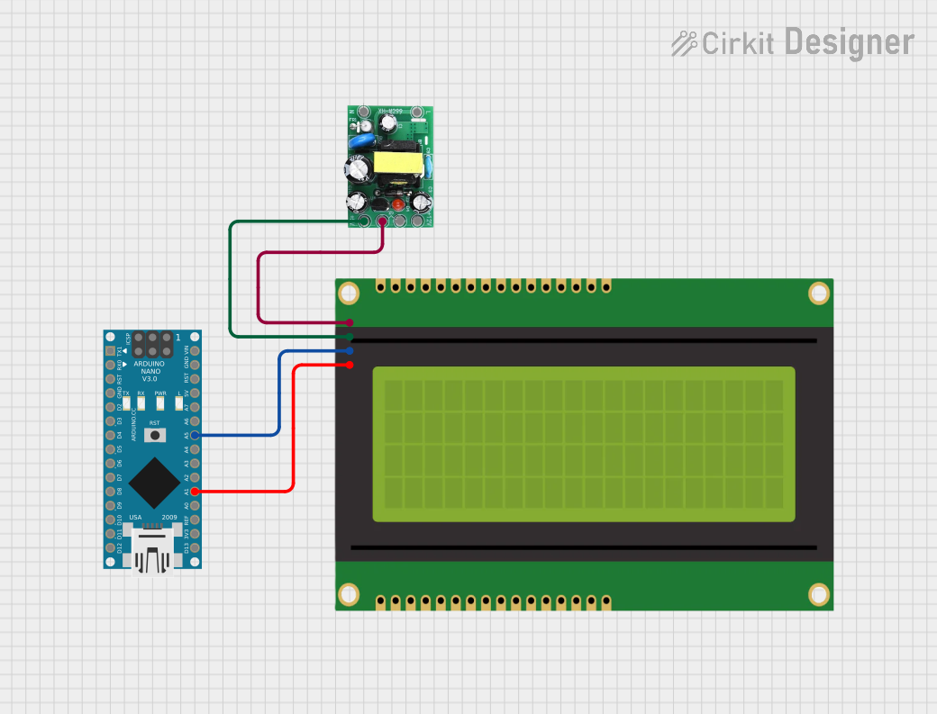 Open Project in Cirkit Designer
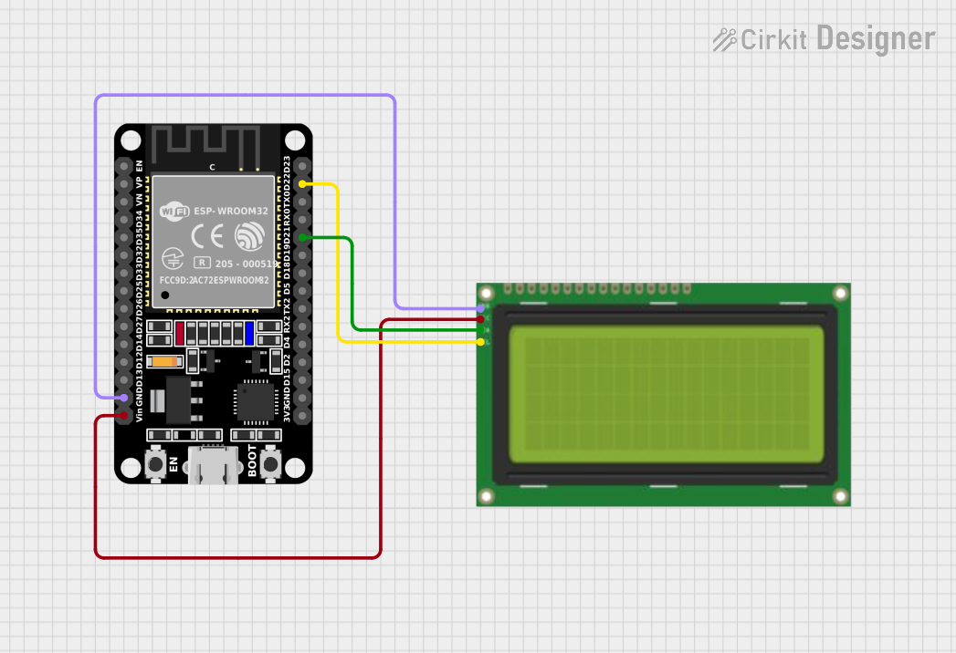 Open Project in Cirkit Designer
Explore Projects Built with LCD 20X4
Open Project in Cirkit DesignerOpen Project in Cirkit DesignerOpen Project in Cirkit DesignerOpen Project in Cirkit DesignerCommon Applications
- Displaying sensor data in IoT projects
- User interfaces for embedded systems
- Menu-driven applications
- Industrial control panels
- Educational and prototyping purposes
Technical Specifications
The following table outlines the key technical details of the LCD 20x4 module:
| Parameter | Specification |
|---|---|
| Display Type | 20x4 Character LCD |
| Controller | HD44780 or compatible |
| Operating Voltage | 4.7V to 5.3V |
| Operating Current | 1.5mA (without backlight) |
| Backlight Voltage | 4.2V to 4.6V |
| Backlight Current | 120mA (typical) |
| Character Size | 5x8 dot matrix |
| Interface Type | Parallel (4-bit or 8-bit mode) |
| Operating Temperature | -20°C to 70°C |
| Dimensions | 98mm x 60mm x 12mm |
Pin Configuration
The LCD 20x4 module typically has 16 pins. The table below describes each pin:
| Pin Number | Pin Name | Description |
|---|---|---|
| 1 | VSS | Ground (0V) |
| 2 | VDD | Power supply (4.7V to 5.3V) |
| 3 | VO | Contrast adjustment (connect to a potentiometer) |
| 4 | RS | Register Select (0: Command, 1: Data) |
| 5 | RW | Read/Write (0: Write, 1: Read) |
| 6 | E | Enable signal (starts data read/write) |
| 7 | D0 | Data bit 0 (used in 8-bit mode only) |
| 8 | D1 | Data bit 1 (used in 8-bit mode only) |
| 9 | D2 | Data bit 2 (used in 8-bit mode only) |
| 10 | D3 | Data bit 3 (used in 8-bit mode only) |
| 11 | D4 | Data bit 4 (used in 4-bit or 8-bit mode) |
| 12 | D5 | Data bit 5 (used in 4-bit or 8-bit mode) |
| 13 | D6 | Data bit 6 (used in 4-bit or 8-bit mode) |
| 14 | D7 | Data bit 7 (used in 4-bit or 8-bit mode) |
| 15 | A (LED+) | Backlight anode (connect to +5V through a resistor if needed) |
| 16 | K (LED-) | Backlight cathode (connect to ground) |
Usage Instructions
Connecting the LCD 20x4 to an Arduino UNO
The LCD 20x4 can be connected to an Arduino UNO using the 4-bit mode to save pins. Below is a typical wiring configuration:
| LCD Pin | Arduino Pin | Description |
|---|---|---|
| VSS | GND | Ground |
| VDD | 5V | Power supply |
| VO | Potentiometer | Contrast adjustment |
| RS | Pin 12 | Register Select |
| RW | GND | Write mode (always 0) |
| E | Pin 11 | Enable signal |
| D4 | Pin 5 | Data bit 4 |
| D5 | Pin 4 | Data bit 5 |
| D6 | Pin 3 | Data bit 6 |
| D7 | Pin 2 | Data bit 7 |
| A (LED+) | 5V | Backlight anode |
| K (LED-) | GND | Backlight cathode |
Arduino Code Example
Below is an example code to display text on the LCD 20x4 using the Arduino LiquidCrystal library:
#include <LiquidCrystal.h>

// Initialize the library with the pins connected to the LCD
// (RS, E, D4, D5, D6, D7)
LiquidCrystal lcd(12, 11, 5, 4, 3, 2);

void setup() {
  // Set up the LCD's number of columns and rows
  lcd.begin(20, 4);

  // Print a message to the LCD
  lcd.setCursor(0, 0); // Set cursor to column 0, row 0
  lcd.print("Hello, World!");

  lcd.setCursor(0, 1); // Set cursor to column 0, row 1
  lcd.print("LCD 20x4 Demo");

  lcd.setCursor(0, 2); // Set cursor to column 0, row 2
  lcd.print("Line 3 Example");

  lcd.setCursor(0, 3); // Set cursor to column 0, row 3
  lcd.print("Line 4 Example");
}

void loop() {
  // Nothing to do here
}
Important Considerations
- Contrast Adjustment: Use a 10kΩ potentiometer to adjust the contrast by connecting it to the VO pin.
- Backlight Current: If the backlight is too bright, use a current-limiting resistor (e.g., 220Ω) between the A (LED+) pin and 5V.
- Power Supply: Ensure a stable 5V power supply to avoid flickering or malfunction.
- 4-bit vs. 8-bit Mode: Use 4-bit mode to save microcontroller pins unless 8-bit mode is specifically required.
Troubleshooting and FAQs
Common Issues
- No Display on the Screen
- Solution: Check the power connections (VDD and VSS). Ensure the contrast is adjusted using the potentiometer.
- Flickering or Unstable Display
- Solution: Verify the power supply voltage and current. Use decoupling capacitors (e.g., 0.1µF) near the power pins.
- Incorrect Characters Displayed
- Solution: Ensure proper wiring of the data pins (D4-D7) and verify the code configuration.
- Backlight Not Working
- Solution: Check the backlight connections (A and K pins). Add a current-limiting resistor if necessary.
FAQs
- Can I use the LCD 20x4 with a 3.3V microcontroller?
- Yes, but you will need a level shifter or resistor divider for the data lines, and the backlight may require a separate 5V supply.
- How do I clear the display?
- Use the
lcd.clear()function in the Arduino LiquidCrystal library to clear the screen.
- Use the
- Can I display custom characters?
- Yes, the HD44780 controller supports custom characters. Use the
lcd.createChar()function to define and display them.
- Yes, the HD44780 controller supports custom characters. Use the
This concludes the documentation for the LCD 20x4 module.