How to Use PCB control 6 servo: Examples, Pinouts, and Specs
Introduction
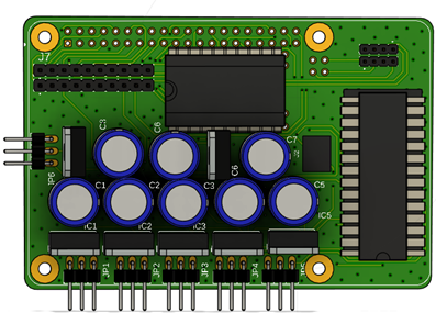
The PCB Control 6 Servo by Vanessa is a specialized printed circuit board designed to control up to six servo motors simultaneously. This component is ideal for applications requiring precise movement and positioning, such as robotics, automation systems, animatronics, and remote-controlled devices. Its compact design and ease of integration make it a versatile choice for both hobbyists and professionals.
Explore Projects Built with PCB control 6 servo


Explore Projects Built with PCB control 6 servo
Common Applications
- Robotic arms and manipulators
- Automated machinery
- Animatronics and motion control systems
- Remote-controlled vehicles and drones
- Educational projects involving servo motor control
Technical Specifications
Key Technical Details
- Input Voltage: 5V to 12V DC
- Maximum Current: 2A per servo channel
- Number of Servo Channels: 6
- Control Signal: PWM (Pulse Width Modulation)
- Communication Interface: Standard servo signal (50Hz PWM)
- Dimensions: 60mm x 40mm
- Operating Temperature: -20°C to 70°C
- Connector Type: 3-pin headers for each servo (Signal, VCC, GND)
Pin Configuration and Descriptions
The PCB Control 6 Servo features a total of 6 servo headers and additional pins for power and control. Below is the pin configuration:
| Pin Name | Description |
|---|---|
| VCC | Power supply input (5V to 12V DC) |
| GND | Ground connection |
| S1 | Signal pin for Servo 1 |
| S2 | Signal pin for Servo 2 |
| S3 | Signal pin for Servo 3 |
| S4 | Signal pin for Servo 4 |
| S5 | Signal pin for Servo 5 |
| S6 | Signal pin for Servo 6 |
Each servo header includes three pins:
- Signal (S): PWM control signal for the servo.
- VCC: Power supply for the servo.
- GND: Ground connection.
Usage Instructions
How to Use the PCB Control 6 Servo in a Circuit
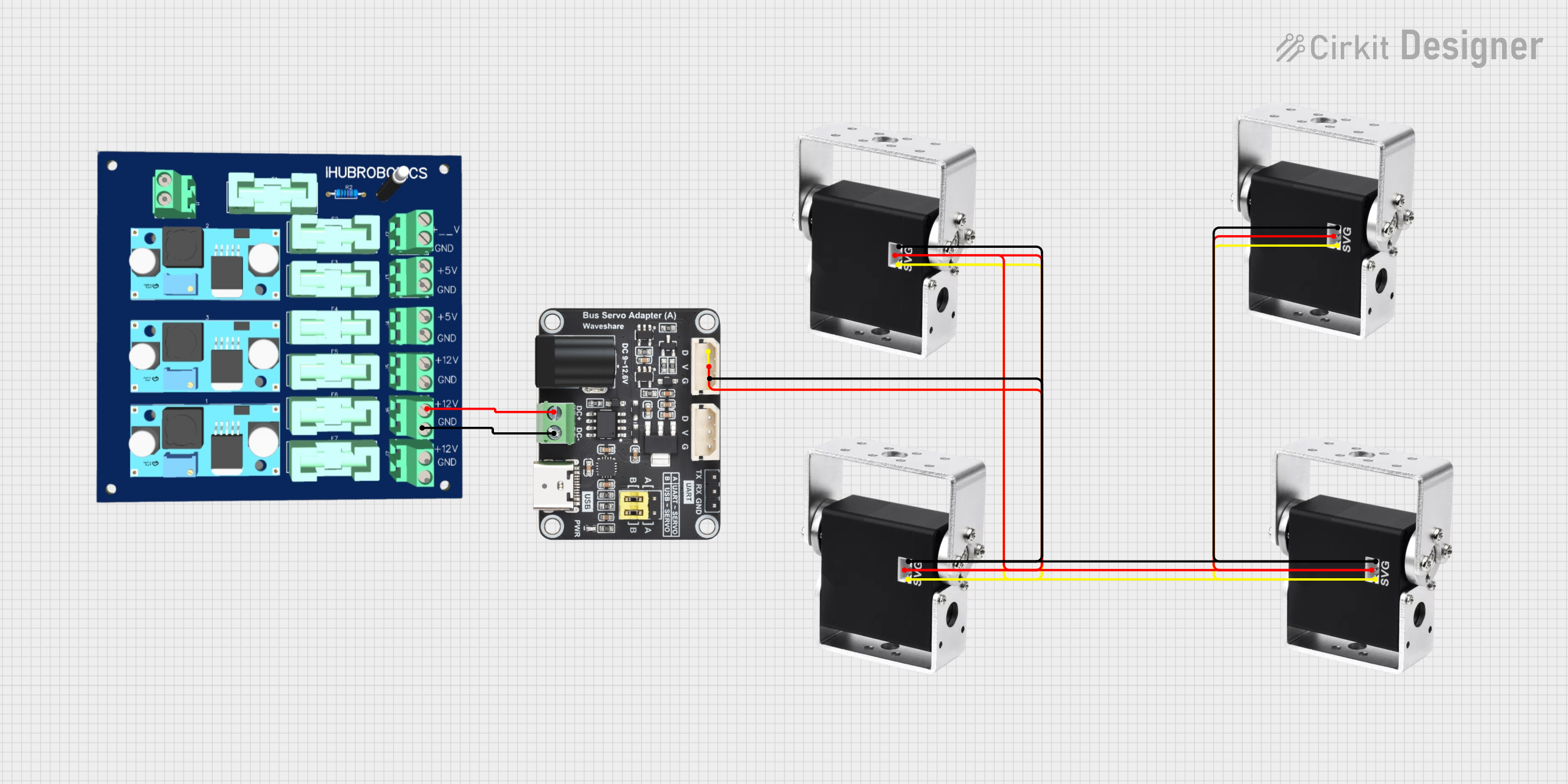
- Power Supply: Connect a DC power source (5V to 12V) to the VCC and GND pins of the PCB. Ensure the power supply can handle the total current draw of all connected servos.
- Servo Connections: Plug the servo motor connectors into the 3-pin headers (S1 to S6). Match the signal, VCC, and GND pins correctly.
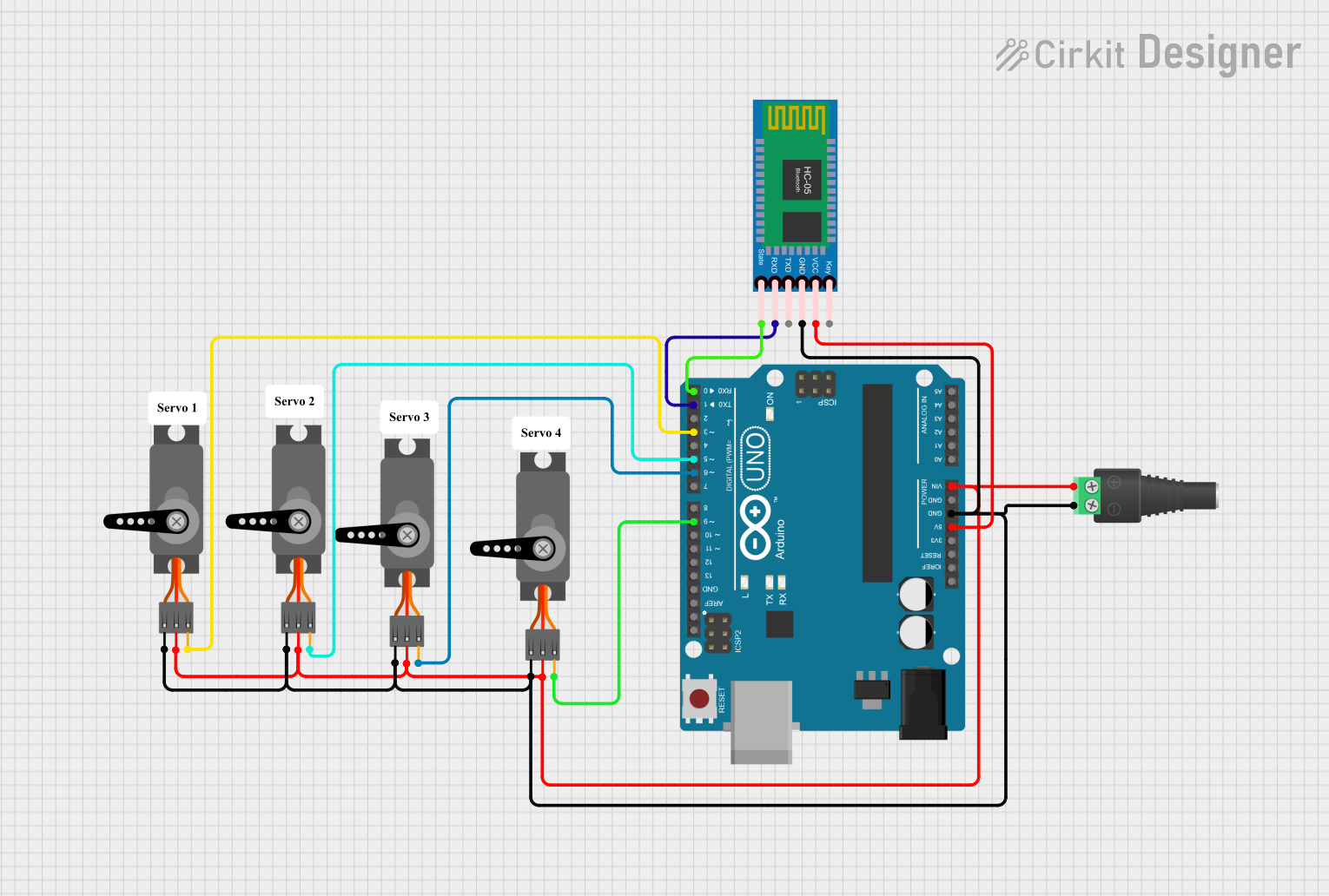
- Control Signal: Use a microcontroller (e.g., Arduino UNO) to send PWM signals to the signal pins (S1 to S6) to control the servo positions.
- Programming: Write a program to generate PWM signals corresponding to the desired servo positions.
Important Considerations
- Power Supply: Ensure the power supply voltage matches the servo motor requirements. Overvoltage can damage the servos or the PCB.
- Current Limitations: Avoid exceeding the maximum current rating of 2A per channel. Use servos with appropriate current ratings.
- Signal Interference: Use short and shielded wires for signal connections to minimize noise and interference.
- Heat Management: If operating multiple servos under heavy load, ensure proper ventilation to prevent overheating.
Example Code for Arduino UNO
Below is an example Arduino sketch to control three servos connected to the PCB Control 6 Servo:
#include <Servo.h> // Include the Servo library

// Create Servo objects for each servo motor
Servo servo1;
Servo servo2;
Servo servo3;

void setup() {
  // Attach the Servo objects to the corresponding signal pins
  servo1.attach(9);  // Servo 1 connected to Arduino pin 9
  servo2.attach(10); // Servo 2 connected to Arduino pin 10
  servo3.attach(11); // Servo 3 connected to Arduino pin 11
}

void loop() {
  // Move Servo 1 to 0 degrees
  servo1.write(0);
  delay(1000); // Wait for 1 second

  // Move Servo 2 to 90 degrees
  servo2.write(90);
  delay(1000); // Wait for 1 second

  // Move Servo 3 to 180 degrees
  servo3.write(180);
  delay(1000); // Wait for 1 second
}
Notes on the Code
- Replace
9,10, and11with the actual Arduino pins connected to the PCB signal pins (S1, S2, S3, etc.). - Adjust the
servo.write()values (0 to 180) to set the desired servo positions.
Troubleshooting and FAQs
Common Issues and Solutions
Servos Not Moving
- Cause: Incorrect power supply or loose connections.
- Solution: Verify the power supply voltage and current. Check all connections for proper contact.
Erratic Servo Movement
- Cause: Signal interference or noise.
- Solution: Use shorter wires for signal connections and ensure proper grounding.
Overheating PCB
- Cause: Excessive current draw from servos.
- Solution: Use servos with lower current ratings or reduce the load on the servos.
Microcontroller Not Responding
- Cause: Incorrect PWM signal configuration.
- Solution: Verify the microcontroller code and ensure the correct pins are used for PWM output.
FAQs
Q: Can I use this PCB with a Raspberry Pi?
A: Yes, the PCB can be used with a Raspberry Pi. However, you may need a PWM driver or library to generate the required PWM signals.
Q: What is the maximum servo size this PCB can handle?
A: The PCB can handle servos with a maximum current draw of 2A per channel. Ensure the total current does not exceed the power supply capacity.
Q: Can I control fewer than six servos?
A: Yes, you can connect and control any number of servos (up to six) as needed.
Q: Is the PCB compatible with digital and analog servos?
A: Yes, the PCB supports both digital and analog servos as long as they operate within the specified voltage and current limits.
This concludes the documentation for the PCB Control 6 Servo by Vanessa. For further assistance, refer to the manufacturer's support resources.