Cirkit Designer Logo
Cirkit Designer
Your all-in-one circuit design IDE
Home / 
Component Documentation

How to Use M5Stack LoRaWAN 868: Examples, Pinouts, and Specs

Image of M5Stack LoRaWAN 868
Cirkit Designer LogoDesign with M5Stack LoRaWAN 868 in Cirkit Designer

Introduction

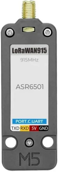
The M5Stack LoRaWAN 868 is a compact development board that integrates a LoRaWAN module designed for long-range wireless communication within the 868 MHz frequency band. This board is ideal for IoT applications requiring low power consumption and long-range data transmission capabilities, such as smart agriculture, environmental monitoring, and smart city infrastructure.

Explore Projects Built with M5Stack LoRaWAN 868

Use Cirkit Designer to design, explore, and prototype these projects online. Some projects support real-time simulation. Click "Open Project" to start designing instantly!
ESP8266 NodeMCU with GPS and LoRa Connectivity
Image of Copy of lora based gps traking: A project utilizing M5Stack LoRaWAN 868 in a practical application
This circuit comprises an ESP8266 NodeMCU microcontroller interfaced with a LoRa Ra-02 SX1278 module for long-range communication and a GPS NEO 6M module for location tracking. The ESP8266 reads GPS data via UART and transmits it using the LoRa module, which is connected via SPI. A 3.7v battery powers the system, making it suitable for remote tracking applications.
Cirkit Designer LogoOpen Project in Cirkit Designer
ESP8266 NodeMCU with LoRa and RS-485 Communication and Ethernet Connectivity
Image of Wiring Diagram LoRa: A project utilizing M5Stack LoRaWAN 868 in a practical application
This circuit serves as a multi-protocol communication hub featuring two ESP8266 NodeMCUs for processing, each connected to a LoRa Ra-02 SX1278 for long-range wireless communication. One NodeMCU is also connected to an RS-485 module for serial communication and a W5500 Ethernet module for network connectivity, with MB102 modules supplying power.
Cirkit Designer LogoOpen Project in Cirkit Designer
ESP8266 NodeMCU Wi-Fi Enabled OLED Display with RYLR896 Communication Module
Image of Smart Irrigation system Rx Side: A project utilizing M5Stack LoRaWAN 868 in a practical application
This circuit features an ESP8266 NodeMCU microcontroller connected to a 0.96" OLED display and an RYLR896 LoRa module. The ESP8266 communicates with the OLED via I2C protocol and interfaces with the LoRa module using UART, enabling wireless data transmission and display capabilities.
Cirkit Designer LogoOpen Project in Cirkit Designer
ESP8266 and LoRa SX1278 Based Wireless Communication Module
Image of Receiver: A project utilizing M5Stack LoRaWAN 868 in a practical application
This circuit integrates a LoRa Ra-02 SX1278 module with an ESP8266 NodeMCU to enable long-range wireless communication. The ESP8266 NodeMCU handles the control and data processing, while the LoRa module provides the capability to transmit and receive data over long distances using LoRa technology.
Cirkit Designer LogoOpen Project in Cirkit Designer

Explore Projects Built with M5Stack LoRaWAN 868

Use Cirkit Designer to design, explore, and prototype these projects online. Some projects support real-time simulation. Click "Open Project" to start designing instantly!
Image of Copy of lora based gps traking: A project utilizing M5Stack LoRaWAN 868 in a practical application
ESP8266 NodeMCU with GPS and LoRa Connectivity
This circuit comprises an ESP8266 NodeMCU microcontroller interfaced with a LoRa Ra-02 SX1278 module for long-range communication and a GPS NEO 6M module for location tracking. The ESP8266 reads GPS data via UART and transmits it using the LoRa module, which is connected via SPI. A 3.7v battery powers the system, making it suitable for remote tracking applications.
Cirkit Designer LogoOpen Project in Cirkit Designer
Image of Wiring Diagram LoRa: A project utilizing M5Stack LoRaWAN 868 in a practical application
ESP8266 NodeMCU with LoRa and RS-485 Communication and Ethernet Connectivity
This circuit serves as a multi-protocol communication hub featuring two ESP8266 NodeMCUs for processing, each connected to a LoRa Ra-02 SX1278 for long-range wireless communication. One NodeMCU is also connected to an RS-485 module for serial communication and a W5500 Ethernet module for network connectivity, with MB102 modules supplying power.
Cirkit Designer LogoOpen Project in Cirkit Designer
Image of Smart Irrigation system Rx Side: A project utilizing M5Stack LoRaWAN 868 in a practical application
ESP8266 NodeMCU Wi-Fi Enabled OLED Display with RYLR896 Communication Module
This circuit features an ESP8266 NodeMCU microcontroller connected to a 0.96" OLED display and an RYLR896 LoRa module. The ESP8266 communicates with the OLED via I2C protocol and interfaces with the LoRa module using UART, enabling wireless data transmission and display capabilities.
Cirkit Designer LogoOpen Project in Cirkit Designer
Image of Receiver: A project utilizing M5Stack LoRaWAN 868 in a practical application
ESP8266 and LoRa SX1278 Based Wireless Communication Module
This circuit integrates a LoRa Ra-02 SX1278 module with an ESP8266 NodeMCU to enable long-range wireless communication. The ESP8266 NodeMCU handles the control and data processing, while the LoRa module provides the capability to transmit and receive data over long distances using LoRa technology.
Cirkit Designer LogoOpen Project in Cirkit Designer

Common Applications and Use Cases

  • Remote sensor data collection
  • Smart agriculture and livestock tracking
  • Environmental monitoring
  • Smart metering and utilities management
  • Asset tracking and logistics

Technical Specifications

Key Technical Details

  • Frequency Band: 868 MHz (suitable for EU regions)
  • LoRaWAN Version: Compatible with LoRaWAN 1.0.2
  • Operating Voltage: 3.3V to 5V
  • Transmit Power: Up to +14 dBm
  • Sensitivity: Down to -137 dBm
  • Range: Up to 10 km (line-of-sight conditions)
  • Interfaces: UART, GPIO, I2C, SPI
  • Antenna: U.FL connector for external antenna

Pin Configuration and Descriptions

Pin Number Name Description
1 GND Ground connection
2 5V 5V power supply input
3 TX UART transmit
4 RX UART receive
5 SCL I2C clock
6 SDA I2C data
7 GPIO General-purpose input/output
8 RST Reset pin
9 NC Not connected/used

Usage Instructions

How to Use the Component in a Circuit

  1. Power Supply: Connect the 5V pin to a 5V power source and GND to the ground.
  2. Antenna: Attach an appropriate 868 MHz antenna to the U.FL connector.
  3. Communication: Connect the TX and RX pins to the corresponding RX and TX pins of your microcontroller or another UART interface.
  4. Programming: Use the provided libraries and API to program the device for LoRaWAN communication.

Important Considerations and Best Practices

  • Ensure that the antenna is properly connected and suited for the 868 MHz band.
  • Use a stable power source to prevent communication errors.
  • Follow regional regulations regarding the use of the 868 MHz frequency band.
  • Implement proper error handling in your code to manage communication retries and message acknowledgment.

Troubleshooting and FAQs

Common Issues Users Might Face

  • No Communication: Check the UART connections and ensure the correct baud rate is set.
  • Low Range: Verify the antenna placement and orientation. Avoid obstacles that could interfere with signal propagation.
  • Joining Network Failure: Ensure that the LoRaWAN keys and device EUI are correctly configured.

Solutions and Tips for Troubleshooting

  • Double-check wiring and solder joints for any loose connections.
  • Use a logic analyzer or oscilloscope to verify UART signals.
  • Test the module with a known working setup to isolate the issue.

FAQs

Q: Can I use the M5Stack LoRaWAN 868 outside of Europe? A: The 868 MHz band is primarily for EU regions. Check local regulations for the appropriate frequency band in your area.

Q: How do I configure the device for my LoRaWAN network? A: Use the provided software libraries and follow the network provider's guidelines to configure the device.

Q: What is the maximum power consumption of the module? A: The module consumes up to 120 mA during transmission, depending on the transmit power setting.

Example Code for Arduino UNO

#include <LoRaWan.h> // Include the LoRaWAN library specific to the module

// Define the pins
#define LORA_TX 3
#define LORA_RX 2

// Initialize the LoRaWAN module
LoRaWan lora = LoRaWan(LORA_TX, LORA_RX);

void setup() {
  Serial.begin(9600); // Start the serial communication
  lora.begin(868E6);  // Initialize LoRaWAN at 868 MHz
  // Set device keys and join the network (OTAA or ABP)
  lora.setDeviceEUI("YOUR_DEVICE_EUI");
  lora.setAppEUI("YOUR_APP_EUI");
  lora.setAppKey("YOUR_APP_KEY");
  lora.join();
}

void loop() {
  // Check if joined to the network
  if (lora.isJoined()) {
    // Prepare the payload
    byte payload[] = "Hello, LoRa!";
    // Send the payload
    lora.sendPacket(payload, sizeof(payload));
  }
  // Wait for a short period before sending the next packet
  delay(10000);
}

Note: The above code is a simplified example to demonstrate basic LoRaWAN communication with an Arduino UNO. You will need to replace "YOUR_DEVICE_EUI", "YOUR_APP_EUI", and "YOUR_APP_KEY" with your actual LoRaWAN network credentials. Additionally, ensure that you have the correct library installed for your specific LoRaWAN module.