How to Use Raspberry Pi Pico: Examples, Pinouts, and Specs
Introduction
The Raspberry Pi Pico is a compact, low-cost microcontroller board developed by Raspberry Pi. It is powered by the RP2040 chip, which features dual-core ARM Cortex-M0+ processors, 264KB of SRAM, and 2MB of onboard flash memory. Designed for versatility, the Pico supports programming in C, C++, MicroPython, and CircuitPython, making it an excellent choice for hobbyists, educators, and professionals alike.
Explore Projects Built with Raspberry Pi Pico
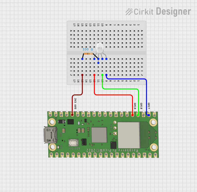
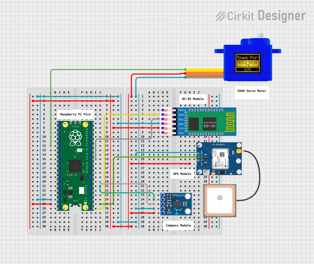

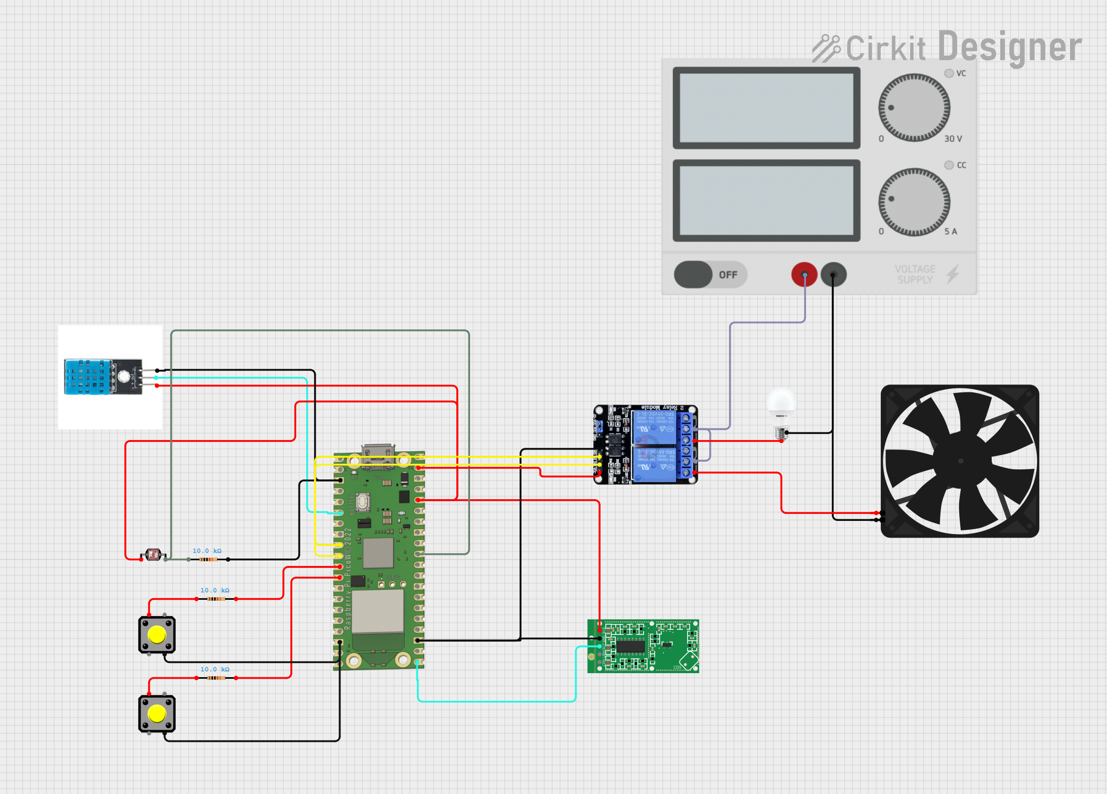
Explore Projects Built with Raspberry Pi Pico
Common Applications and Use Cases
- IoT (Internet of Things) devices
- Robotics and automation
- Sensor interfacing and data logging
- Prototyping and embedded systems development
- Educational projects for learning programming and electronics
Technical Specifications
The Raspberry Pi Pico is packed with features that make it a powerful and flexible microcontroller board. Below are its key technical details:
Key Technical Details
- Processor: Dual-core ARM Cortex-M0+ @ 133 MHz
- Memory: 264KB SRAM, 2MB onboard QSPI flash
- GPIO Pins: 26 multi-function GPIO pins (3.3V logic level)
- Interfaces: I2C, SPI, UART, PWM, ADC (3 channels), USB 1.1
- Power Supply: 1.8V to 5.5V (via micro-USB or VSYS pin)
- Operating Temperature: -20°C to +85°C
- Dimensions: 51mm x 21mm x 1mm
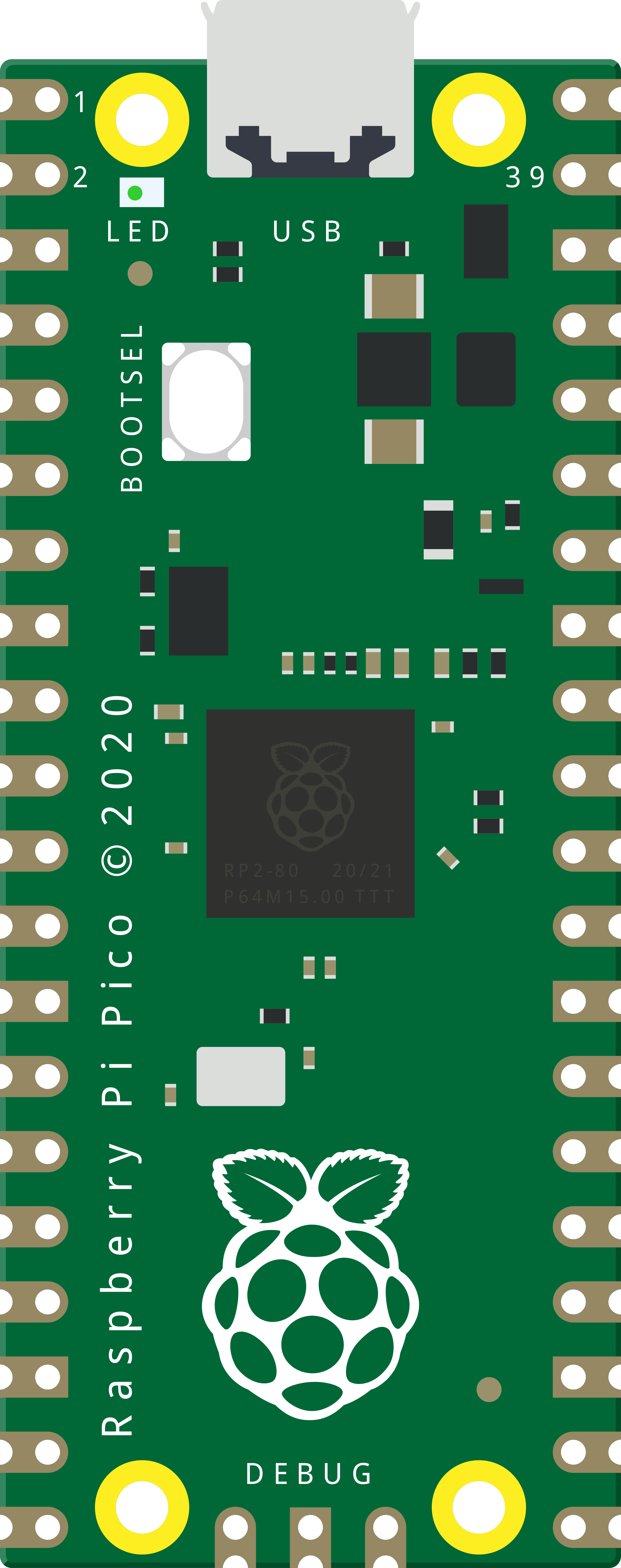
Pin Configuration and Descriptions
The Raspberry Pi Pico has 40 pins, including power, ground, and GPIO pins. Below is a summary of the pin configuration:
| Pin Number | Pin Name | Description |
|---|---|---|
| 1 | GP0 | GPIO Pin 0, supports I2C0 SDA, UART0 TX |
| 2 | GP1 | GPIO Pin 1, supports I2C0 SCL, UART0 RX |
| 3 | GND | Ground |
| 4 | GP2 | GPIO Pin 2, supports PWM, SPI0 SCK |
| 5 | GP3 | GPIO Pin 3, supports PWM, SPI0 TX |
| ... | ... | ... (Refer to the official datasheet for details) |
| 39 | 3V3(OUT) | 3.3V Output |
| 40 | GND | Ground |
For a complete pinout diagram, refer to the official Raspberry Pi Pico documentation.
Usage Instructions
The Raspberry Pi Pico is easy to use and can be programmed using various languages. Below are the steps to get started and some best practices:
How to Use the Raspberry Pi Pico in a Circuit
Powering the Pico:
- Connect the Pico to your computer via a micro-USB cable for power and programming.
- Alternatively, supply power through the VSYS pin (1.8V to 5.5V).
Programming the Pico:
- Install the MicroPython firmware by holding the BOOTSEL button while connecting the Pico to your computer.
- Drag and drop the firmware file onto the Pico's storage drive.
- Use a Python IDE (e.g., Thonny) to write and upload code.
Connecting Components:
- Use the GPIO pins to connect sensors, actuators, or other peripherals.
- Ensure components operate at 3.3V logic levels to avoid damaging the Pico.
Example: Blinking an LED with MicroPython
Import the Pin module from the machine library
from machine import Pin from time import sleep
Set up GPIO Pin 25 (onboard LED) as an output pin
led = Pin(25, Pin.OUT)
Blink the LED in an infinite loop
while True: led.value(1) # Turn the LED on sleep(1) # Wait for 1 second led.value(0) # Turn the LED off sleep(1) # Wait for 1 second
Important Considerations and Best Practices
- Always check the voltage and current ratings of connected components to avoid damage.
- Use level shifters if interfacing with 5V logic devices.
- Avoid shorting GPIO pins or connecting them directly to power or ground.
Troubleshooting and FAQs
Common Issues and Solutions
Pico Not Detected by Computer:
- Ensure the BOOTSEL button is held down while connecting the Pico to the computer.
- Check the USB cable for data transfer capability (some cables are power-only).
Code Not Running on Startup:
- Save your script as
main.pyormain.uf2on the Pico to run it automatically on boot.
- Save your script as
Overheating or Malfunctioning:
- Verify that the power supply voltage is within the acceptable range (1.8V to 5.5V).
- Check for short circuits or incorrect wiring.
FAQs
Can I use the Pico with Arduino IDE?
Yes, the Pico is compatible with the Arduino IDE. Install the RP2040 board package to get started.What is the maximum current output of the GPIO pins?
Each GPIO pin can source or sink up to 12mA, with a total maximum current of 50mA for all pins combined.Can I use the Pico for battery-powered projects?
Yes, the Pico can be powered via the VSYS pin using a battery (e.g., LiPo or AA batteries).
For more detailed information, refer to the official Raspberry Pi Pico datasheet and documentation.