How to Use Kamoer Peristaltic Pump 5-Wire Harness: Examples, Pinouts, and Specs
Introduction
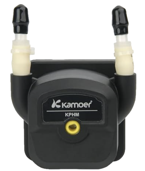
The Kamoer Peristaltic Pump 5-Wire Harness (Part ID: KPHM600-12B3B17) is a specialized wiring harness designed to interface with Kamoer peristaltic pumps. This harness simplifies the connection process, enabling precise control and operation of the pump in applications such as fluid dispensing, dosing, and laboratory automation. Its robust design ensures reliable performance in demanding environments.
Explore Projects Built with Kamoer Peristaltic Pump 5-Wire Harness
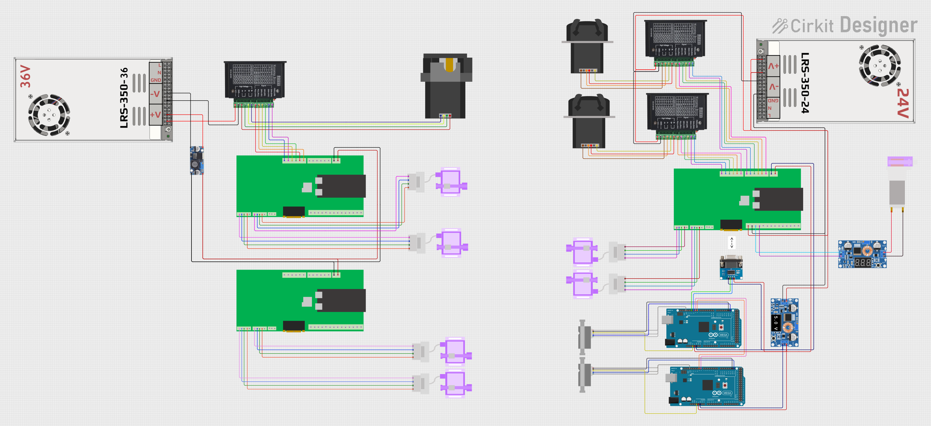
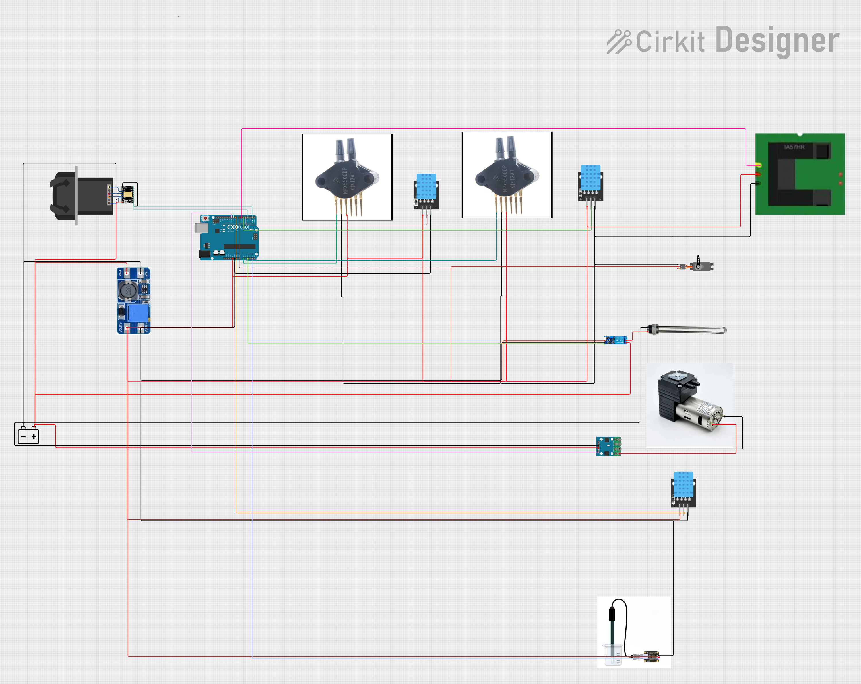
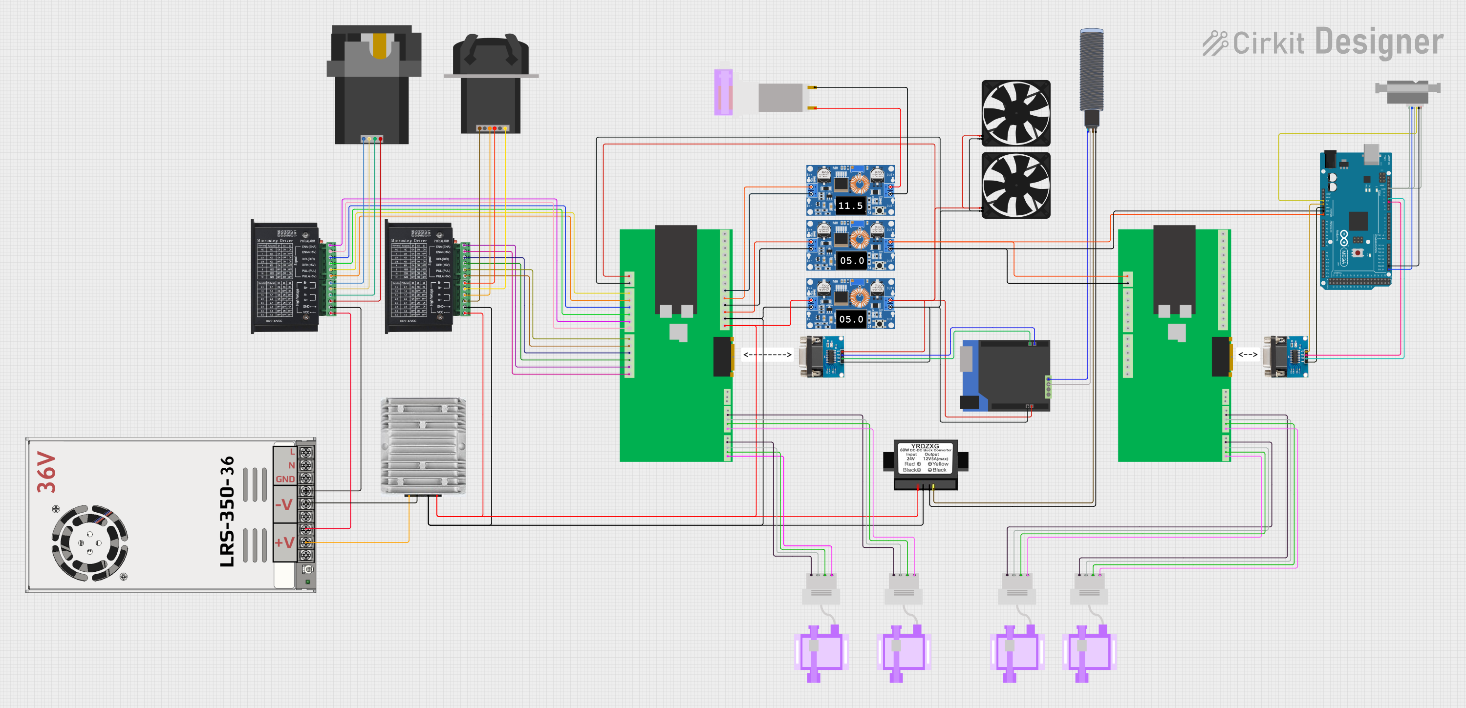
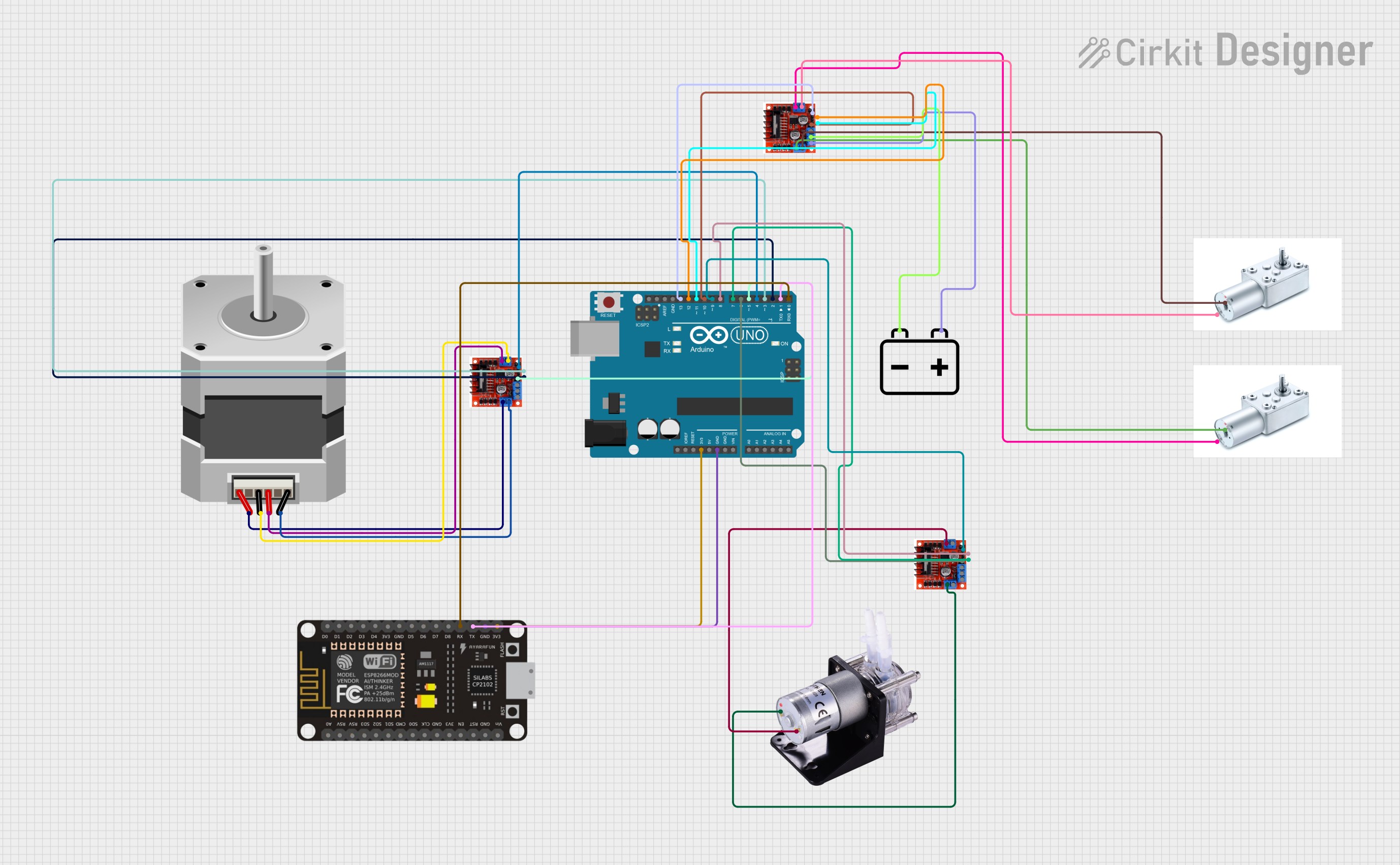
Explore Projects Built with Kamoer Peristaltic Pump 5-Wire Harness
Common Applications
- Fluid dispensing in medical and laboratory equipment
- Dosing systems for aquariums and hydroponics
- Industrial automation requiring precise liquid handling
- Food and beverage processing systems
Technical Specifications
Key Technical Details
- Manufacturer: Kamoer
- Part ID: KPHM600-12B3B17
- Number of Wires: 5
- Wire Length: 600 mm (23.6 inches)
- Connector Type: JST XH 5-pin connector
- Wire Gauge: 24 AWG
- Voltage Rating: 12V DC (compatible with Kamoer peristaltic pumps)
- Current Rating: Up to 2A
- Operating Temperature: -20°C to 60°C (-4°F to 140°F)
- Insulation Material: PVC
Pin Configuration and Descriptions
The 5-wire harness is color-coded for easy identification and connection. Below is the pinout configuration:
| Pin Number | Wire Color | Function | Description |
|---|---|---|---|
| 1 | Red | VCC (+12V) | Supplies power to the pump motor. |
| 2 | Black | GND | Ground connection for the pump. |
| 3 | Yellow | Direction Control (DIR) | Controls the direction of the pump (e.g., clockwise or counterclockwise). |
| 4 | Green | Pulse Signal (PUL) | Receives pulse signals to control the pump's speed and operation. |
| 5 | Blue | Enable Signal (EN) | Enables or disables the pump operation. |
Usage Instructions
How to Use the Component in a Circuit
Connect the Harness to the Pump:
Attach the JST XH 5-pin connector to the corresponding port on the Kamoer peristaltic pump. Ensure the connector is securely seated.Wire the Harness to a Controller:
- Connect the Red (VCC) wire to a 12V DC power supply.
- Connect the Black (GND) wire to the ground of the power supply and controller.
- Connect the Yellow (DIR) wire to a digital output pin on your microcontroller to control the pump's direction.
- Connect the Green (PUL) wire to a PWM-capable digital output pin to control the pump's speed.
- Connect the Blue (EN) wire to a digital output pin to enable or disable the pump.
Program the Controller:
Use a microcontroller (e.g., Arduino UNO) to send control signals to the pump. Below is an example Arduino sketch:
// Define pin connections for the Kamoer 5-wire harness
const int dirPin = 2;  // Direction control pin
const int pulPin = 3;  // Pulse signal pin
const int enPin = 4;   // Enable signal pin

void setup() {
  // Set pin modes
  pinMode(dirPin, OUTPUT);
  pinMode(pulPin, OUTPUT);
  pinMode(enPin, OUTPUT);

  // Initialize pump in disabled state
  digitalWrite(enPin, LOW);  // Disable pump
  digitalWrite(dirPin, LOW); // Set initial direction
}

void loop() {
  // Enable the pump
  digitalWrite(enPin, HIGH);

  // Set pump direction to clockwise
  digitalWrite(dirPin, LOW);

  // Generate pulse signals to control pump speed
  for (int i = 0; i < 1000; i++) {
    digitalWrite(pulPin, HIGH);
    delayMicroseconds(500); // Adjust delay for speed control
    digitalWrite(pulPin, LOW);
    delayMicroseconds(500);
  }

  // Disable the pump after operation
  digitalWrite(enPin, LOW);

  // Wait before the next operation
  delay(2000);
}
Important Considerations and Best Practices
- Power Supply: Ensure the power supply provides a stable 12V DC output with sufficient current capacity (at least 2A).
- Signal Integrity: Use short, shielded wires for signal connections to minimize noise and interference.
- Direction Control: Toggle the DIR pin to change the pump's direction. Ensure the pump is stopped before changing direction to avoid damage.
- Enable Signal: Use the EN pin to disable the pump when not in use, reducing power consumption and wear.
- Heat Management: Avoid prolonged operation at maximum speed to prevent overheating.
Troubleshooting and FAQs
Common Issues and Solutions
| Issue | Possible Cause | Solution |
|---|---|---|
| Pump does not start | - Power supply not connected or insufficient - EN pin not set to HIGH |
- Verify power supply connections and voltage - Set EN pin to HIGH |
| Pump runs in the wrong direction | DIR pin signal is incorrect | Toggle the DIR pin to change the direction |
| Pump speed is inconsistent | - Noise on PUL signal - Insufficient power supply |
- Use shielded cables for PUL signal - Ensure power supply meets requirements |
| Pump overheats during operation | Prolonged operation at high speed | Reduce operating speed or add cooling measures |
| No response from the pump | Loose or incorrect wiring | Double-check all connections and ensure the harness is securely attached |
FAQs
Can I use a different voltage supply?
No, the harness and pump are designed for 12V DC operation. Using a different voltage may damage the pump.What happens if I leave the EN pin floating?
The pump may behave unpredictably. Always set the EN pin to HIGH or LOW explicitly.Can I extend the wire length?
Yes, but ensure the extended wires are of the same gauge (24 AWG) and use shielded cables to minimize signal degradation.Is the harness compatible with other pumps?
This harness is specifically designed for Kamoer peristaltic pumps. Compatibility with other pumps is not guaranteed.
By following this documentation, you can effectively integrate the Kamoer Peristaltic Pump 5-Wire Harness into your projects for precise fluid control and operation.