Cirkit Designer Logo
Cirkit Designer
Your all-in-one circuit design IDE
Home / 
Component Documentation

How to Use LM2596 Step Down Module: Examples, Pinouts, and Specs

Image of LM2596 Step Down Module
Cirkit Designer LogoDesign with LM2596 Step Down Module in Cirkit Designer

Introduction

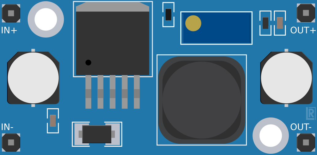
The LM2596 Step Down Module is a highly efficient voltage regulator designed to convert a higher input voltage to a lower, stable output voltage. This module is based on the LM2596 regulator IC and is widely used in electronics to power sensitive components that require a specific operating voltage. Common applications include battery-operated devices, power supplies, and as a part of embedded systems where voltage regulation is critical.

Explore Projects Built with LM2596 Step Down Module

Use Cirkit Designer to design, explore, and prototype these projects online. Some projects support real-time simulation. Click "Open Project" to start designing instantly!
Voltage Regulation System with MT3608 Boost and LM2596 Buck Converters
Image of solar system router ups: A project utilizing LM2596 Step Down Module in a practical application
This circuit consists of two MT3608 boost converters and an LM2596 step-down module, each connected to separate 12V power supplies. The MT3608 modules are configured to step up the voltage from their respective power supplies, while the LM2596 module steps down the voltage from a 12V battery. Diodes are used to ensure correct current flow direction, potentially for protection or isolation between different parts of the circuit.
Cirkit Designer LogoOpen Project in Cirkit Designer
Battery-Powered UPS with Step-Down Buck Converter and BMS
Image of Mini ups: A project utilizing LM2596 Step Down Module in a practical application
This circuit is a power management system that steps down a 240V AC input to a lower DC voltage using a buck converter, which then powers a 40W UPS. The UPS is controlled by a rocker switch and is backed up by a battery management system (BMS) connected to three 3.7V batteries in series, ensuring continuous power supply.
Cirkit Designer LogoOpen Project in Cirkit Designer
Battery-Powered DC-DC Converter System for Multi-Voltage Power Distribution
Image of test 1 ih: A project utilizing LM2596 Step Down Module in a practical application
This circuit converts a 38.5V battery output to multiple lower voltage levels using a series of DC-DC converters and a power module. It includes an emergency stop switch for safety and distributes power to various components such as a relay module, USB ports, and a bus servo adaptor.
Cirkit Designer LogoOpen Project in Cirkit Designer
ESP32-Based Solar-Powered Current Monitoring System with OLED Display
Image of Solar Tracker and Monitoring System: A project utilizing LM2596 Step Down Module in a practical application
This circuit features an ESP32 microcontroller interfaced with a 0.96" OLED display, multiple LDR sensors with voltage dividers, an ACS712 current sensor, and two servomotors. The ESP32 reads analog values from the LDRs and the current sensor, and controls the servomotors. The LM2596 module steps down voltage for the circuit, which is powered by a combination of a solar panel and a 12V battery, with the current sensor monitoring the load current.
Cirkit Designer LogoOpen Project in Cirkit Designer

Explore Projects Built with LM2596 Step Down Module

Use Cirkit Designer to design, explore, and prototype these projects online. Some projects support real-time simulation. Click "Open Project" to start designing instantly!
Image of solar system router ups: A project utilizing LM2596 Step Down Module in a practical application
Voltage Regulation System with MT3608 Boost and LM2596 Buck Converters
This circuit consists of two MT3608 boost converters and an LM2596 step-down module, each connected to separate 12V power supplies. The MT3608 modules are configured to step up the voltage from their respective power supplies, while the LM2596 module steps down the voltage from a 12V battery. Diodes are used to ensure correct current flow direction, potentially for protection or isolation between different parts of the circuit.
Cirkit Designer LogoOpen Project in Cirkit Designer
Image of Mini ups: A project utilizing LM2596 Step Down Module in a practical application
Battery-Powered UPS with Step-Down Buck Converter and BMS
This circuit is a power management system that steps down a 240V AC input to a lower DC voltage using a buck converter, which then powers a 40W UPS. The UPS is controlled by a rocker switch and is backed up by a battery management system (BMS) connected to three 3.7V batteries in series, ensuring continuous power supply.
Cirkit Designer LogoOpen Project in Cirkit Designer
Image of test 1 ih: A project utilizing LM2596 Step Down Module in a practical application
Battery-Powered DC-DC Converter System for Multi-Voltage Power Distribution
This circuit converts a 38.5V battery output to multiple lower voltage levels using a series of DC-DC converters and a power module. It includes an emergency stop switch for safety and distributes power to various components such as a relay module, USB ports, and a bus servo adaptor.
Cirkit Designer LogoOpen Project in Cirkit Designer
Image of Solar Tracker and Monitoring System: A project utilizing LM2596 Step Down Module in a practical application
ESP32-Based Solar-Powered Current Monitoring System with OLED Display
This circuit features an ESP32 microcontroller interfaced with a 0.96" OLED display, multiple LDR sensors with voltage dividers, an ACS712 current sensor, and two servomotors. The ESP32 reads analog values from the LDRs and the current sensor, and controls the servomotors. The LM2596 module steps down voltage for the circuit, which is powered by a combination of a solar panel and a 12V battery, with the current sensor monitoring the load current.
Cirkit Designer LogoOpen Project in Cirkit Designer

Technical Specifications

Key Technical Details

  • Input Voltage Range: 4.5V to 40V
  • Output Voltage Range: 1.23V to 37V (adjustable via onboard potentiometer)
  • Output Current: Up to 3A (with heat sink), 2A (without heat sink)
  • Switching Frequency: 150 kHz
  • Efficiency: Up to 92%
  • Operating Temperature: -40°C to +85°C

Pin Configuration and Descriptions

Pin Number Name Description
1 VIN Input voltage (4.5V to 40V)
2 GND Ground connection
3 VOUT Regulated output voltage (1.23V to 37V)
4 ADJ Adjust pin (connected to onboard potentiometer for voltage adjustment)

Usage Instructions

How to Use the Component in a Circuit

  1. Connect the Input Voltage:

    • Connect the positive terminal of your input voltage source to the VIN pin.
    • Connect the negative terminal to the GND pin.
  2. Adjust the Output Voltage:

    • Before connecting your load, use a multimeter to measure the output voltage.
    • Turn the onboard potentiometer clockwise or counterclockwise to adjust the VOUT to your desired level.
  3. Connect the Load:

    • Connect the positive terminal of your load to the VOUT pin.
    • Connect the negative terminal of your load to the GND pin.
  4. Power On:

    • Once everything is connected and the output voltage is set, power on the input voltage source.

Important Considerations and Best Practices

  • Heat Dissipation: Ensure adequate heat dissipation when drawing high currents. Attach a heat sink if the current exceeds 2A.
  • Capacitive Load: Be cautious with highly capacitive loads as they can affect the stability of the voltage regulator.
  • Input Voltage: Never exceed the maximum input voltage of 40V to prevent damage to the module.
  • Output Voltage: Always adjust the output voltage before connecting the load to avoid potential damage.
  • Short Circuit Protection: While the LM2596 has built-in short circuit protection, it's advisable to add a fuse on the input side for additional safety.

Troubleshooting and FAQs

Common Issues

  • Output Voltage is Too High or Too Low:

    • Check the potentiometer adjustment.
    • Ensure that the input voltage is within the specified range.
  • Module is Overheating:

    • Reduce the load current or attach a heat sink to the module.
    • Improve air circulation around the module.
  • No Output Voltage:

    • Verify connections to VIN, GND, and VOUT.
    • Check for any short circuits or damaged components.

FAQs

Q: Can I use the LM2596 module to charge batteries? A: Yes, but you must ensure the output voltage is correctly set for the battery type and that the charging current does not exceed the module's limit.

Q: Is the output voltage fixed or adjustable? A: The output voltage is adjustable via the onboard potentiometer.

Q: How do I know if I need a heat sink? A: If the module is too hot to touch or if you are drawing more than 2A, a heat sink is recommended.

Q: Can I use this module with an Arduino? A: Yes, it can be used to provide a stable voltage supply to an Arduino or its peripherals.

Example Arduino Connection Code

// No specific code is required for the LM2596 as it is a hardware component.
// However, ensure that the output voltage from the LM2596 is within the
// operating voltage range of the Arduino (typically 5V or 3.3V).

void setup() {
  // Initialize serial communication at 9600 bits per second:
  Serial.begin(9600);
}

void loop() {
  // The LM2596 module will continuously provide power to the Arduino,
  // so you can run your desired code here.
  Serial.println("LM2596 is powering the Arduino!");
  delay(1000); // Wait for 1 second
}

Remember to adjust the LM2596's output voltage to match the voltage requirement of your Arduino board (5V for most boards) before connecting it to the VOUT and GND pins.