How to Use ESP8266 NodeMCU custom size: Examples, Pinouts, and Specs
Introduction
The ESP8266 NodeMCU is a versatile Wi-Fi microcontroller board based on the ESP8266 chip, designed specifically for Internet of Things (IoT) applications. It combines a powerful microcontroller with built-in Wi-Fi capabilities, making it ideal for projects requiring wireless connectivity. The custom size variant allows for tailored dimensions to fit specific project requirements, offering flexibility for compact or space-constrained designs.
Explore Projects Built with ESP8266 NodeMCU custom size
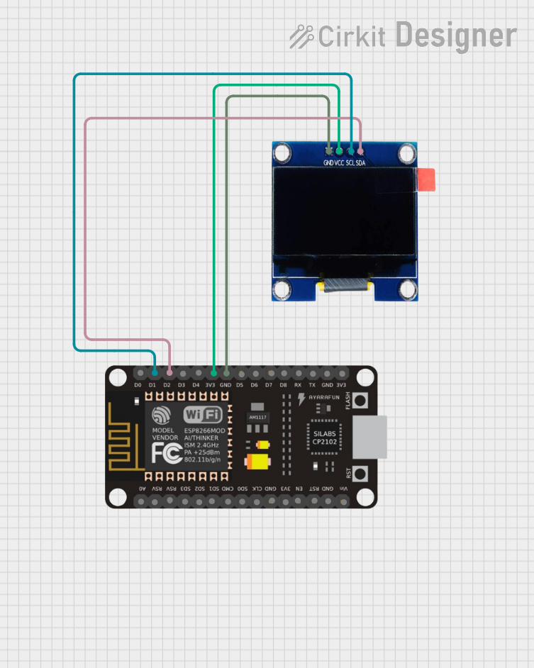

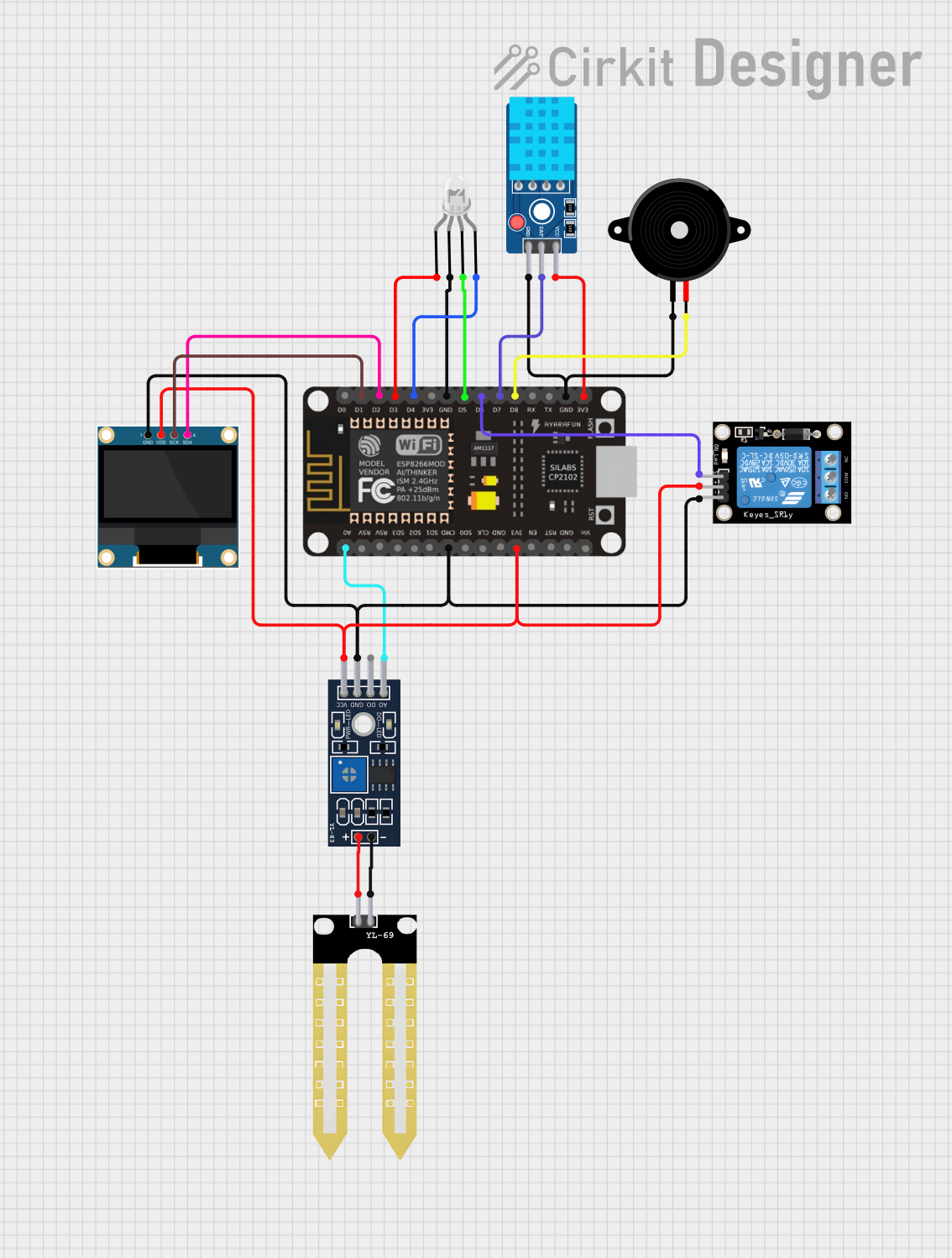
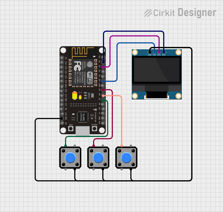
Explore Projects Built with ESP8266 NodeMCU custom size
Common Applications and Use Cases
- Home automation systems (e.g., smart lights, thermostats)
- IoT sensor networks
- Wireless data logging and monitoring
- Remote control of devices via mobile apps or web interfaces
- Prototyping and development of connected devices
Technical Specifications
Key Technical Details
- Microcontroller: ESP8266 (Tensilica L106 32-bit processor)
- Clock Speed: 80 MHz (can be overclocked to 160 MHz)
- Flash Memory: 4 MB (customizable in some variants)
- Operating Voltage: 3.3V
- Input Voltage: 4.5V–10V (via VIN pin) or 5V (via USB)
- Wi-Fi Standards: 802.11 b/g/n
- GPIO Pins: Up to 11 (configurable)
- Communication Protocols: UART, SPI, I2C, PWM
- USB Interface: Built-in CP2102 or CH340 USB-to-serial converter
- Power Consumption: ~70 mA (active), ~10 µA (deep sleep mode)
- Dimensions: Customizable to fit project needs
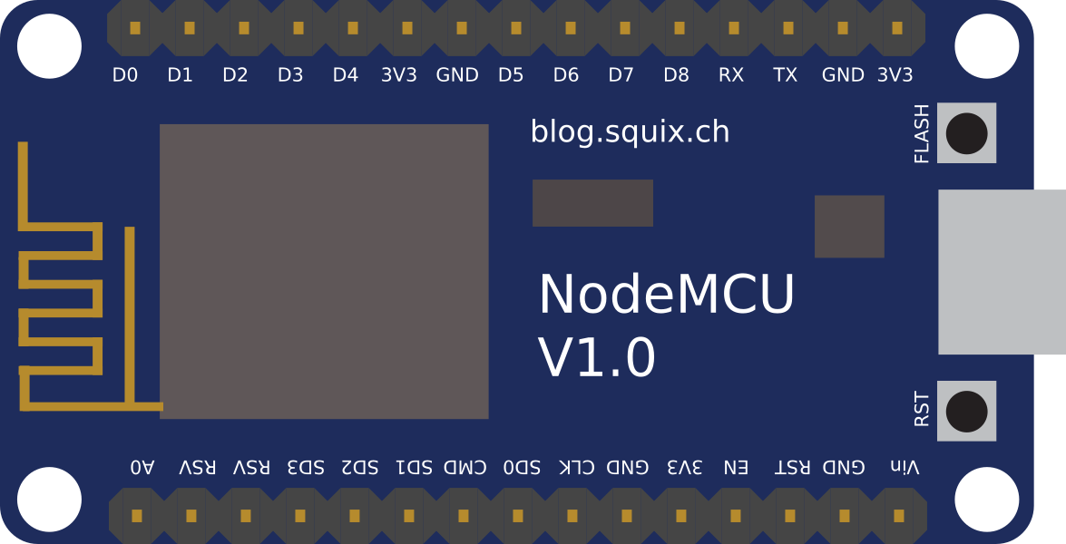
Pin Configuration and Descriptions
The ESP8266 NodeMCU custom size variant typically includes the following pinout:
| Pin | Name | Description |
|---|---|---|
| 1 | VIN | Input voltage (4.5V–10V). Powers the board when USB is not connected. |
| 2 | GND | Ground pin. Connect to the ground of the circuit. |
| 3 | 3V3 | 3.3V output. Can power external components (max 50 mA). |
| 4 | D0 (GPIO16) | General-purpose I/O pin. Can also be used for deep sleep wake-up. |
| 5 | D1 (GPIO5) | General-purpose I/O pin. Commonly used for I2C SCL. |
| 6 | D2 (GPIO4) | General-purpose I/O pin. Commonly used for I2C SDA. |
| 7 | D3 (GPIO0) | General-purpose I/O pin. Must be HIGH during boot to avoid boot mode issues. |
| 8 | D4 (GPIO2) | General-purpose I/O pin. Built-in LED is connected to this pin. |
| 9 | RX (GPIO3) | UART receive pin. Used for serial communication. |
| 10 | TX (GPIO1) | UART transmit pin. Used for serial communication. |
| 11 | A0 | Analog input pin. Reads voltages from 0–1V (use a voltage divider for higher). |
Note: The number of GPIO pins available may vary depending on the custom size configuration.
Usage Instructions
How to Use the ESP8266 NodeMCU in a Circuit
Powering the Board:
- Use the USB port for development and programming.
- For standalone operation, supply 4.5V–10V to the VIN pin or 3.3V to the 3V3 pin.
Connecting to Wi-Fi:
- Use the built-in Wi-Fi module to connect to a network. Ensure the SSID and password are correctly configured in your code.
Programming:
- Install the Arduino IDE and add the ESP8266 board package.
- Select "NodeMCU 1.0 (ESP-12E Module)" as the board type.
- Connect the board to your computer via USB and upload your code.
GPIO Usage:
- Configure GPIO pins as input or output in your code.
- Avoid using GPIO0, GPIO2, and GPIO15 for critical functions, as they affect the boot process.
Important Considerations and Best Practices
- Voltage Levels: Ensure all connected components operate at 3.3V logic levels. Use level shifters if interfacing with 5V devices.
- Deep Sleep Mode: Use deep sleep mode to conserve power in battery-operated projects.
- Custom Size: Verify the pinout and dimensions of your custom-sized board before designing your PCB or enclosure.
- Boot Mode: Ensure GPIO0 is HIGH during boot to avoid entering flash mode unintentionally.
Example Code for Arduino IDE
The following example demonstrates how to connect the ESP8266 NodeMCU to a Wi-Fi network and control the built-in LED:
#include <ESP8266WiFi.h>

// Replace with your network credentials
const char* ssid = "Your_SSID";
const char* password = "Your_PASSWORD";

void setup() {
  Serial.begin(115200); // Initialize serial communication
  pinMode(LED_BUILTIN, OUTPUT); // Set built-in LED pin as output

  // Connect to Wi-Fi
  Serial.print("Connecting to Wi-Fi");
  WiFi.begin(ssid, password);
  while (WiFi.status() != WL_CONNECTED) {
    delay(500);
    Serial.print(".");
  }
  Serial.println("\nWi-Fi connected!");
}

void loop() {
  // Blink the built-in LED
  digitalWrite(LED_BUILTIN, LOW); // Turn LED on
  delay(1000); // Wait for 1 second
  digitalWrite(LED_BUILTIN, HIGH); // Turn LED off
  delay(1000); // Wait for 1 second
}
Troubleshooting and FAQs
Common Issues and Solutions
Board Not Detected by Computer:
- Ensure the correct USB driver (CP2102 or CH340) is installed.
- Try a different USB cable or port.
Wi-Fi Connection Fails:
- Double-check the SSID and password in your code.
- Ensure the router is within range and supports 2.4 GHz Wi-Fi (ESP8266 does not support 5 GHz).
Code Upload Fails:
- Verify the correct board and port are selected in the Arduino IDE.
- Press and hold the FLASH button on the board while uploading.
GPIO Pin Issues:
- Avoid using GPIO0, GPIO2, and GPIO15 for critical functions, as they affect the boot process.
- Check for conflicting pin assignments in your code.
FAQs
Can I use the ESP8266 NodeMCU with 5V sensors?
- No, the ESP8266 operates at 3.3V logic levels. Use a level shifter for 5V sensors.
What is the maximum range of the Wi-Fi module?
- The range is approximately 30 meters indoors and 100 meters outdoors, depending on obstacles and interference.
How do I enable deep sleep mode?
- Connect GPIO16 to the RESET pin and use the
ESP.deepSleep()function in your code.
- Connect GPIO16 to the RESET pin and use the
Can I customize the board size and pinout?
- Yes, custom-sized variants are available. Contact your supplier for details.