How to Use Connector 2 In 2 Out: Examples, Pinouts, and Specs
Introduction
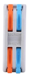
The Connector 2 In 2 Out is a versatile electronic component designed to route two input signals to two separate output paths. This component is commonly used in circuits where signal distribution or splitting is required. It provides a simple and reliable way to manage multiple signal paths without the need for complex circuitry.
Explore Projects Built with Connector 2 In 2 Out
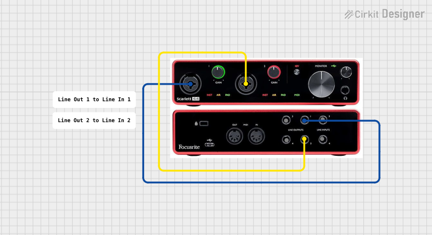


Explore Projects Built with Connector 2 In 2 Out
Common Applications and Use Cases
- Signal splitting in audio or data transmission systems
- Routing signals in testing and prototyping environments
- Distributing power or control signals in multi-device setups
- Simplifying wiring in modular electronic systems
Technical Specifications
The Connector 2 In 2 Out is a passive component with no active electronic parts. Below are its key technical details:
| Parameter | Value |
|---|---|
| Maximum Voltage | 30V DC |
| Maximum Current | 2A |
| Contact Resistance | ≤ 50 mΩ |
| Insulation Resistance | ≥ 100 MΩ |
| Operating Temperature | -20°C to +70°C |
| Connector Type | Screw terminal or pin header |
| Dimensions | 25mm x 15mm x 10mm |
Pin Configuration and Descriptions
The Connector 2 In 2 Out typically has four terminals or pins. The table below describes the pin configuration:
| Pin | Label | Description |
|---|---|---|
| 1 | IN1 | First input signal terminal |
| 2 | IN2 | Second input signal terminal |
| 3 | OUT1 | Output terminal corresponding to IN1 |
| 4 | OUT2 | Output terminal corresponding to IN2 |
Usage Instructions
How to Use the Connector 2 In 2 Out in a Circuit
- Identify the Terminals: Locate the IN1, IN2, OUT1, and OUT2 terminals on the connector.
- Connect Input Signals: Attach the input signals to the IN1 and IN2 terminals. Ensure the polarity and signal type match the circuit requirements.
- Connect Output Paths: Connect the desired output paths to the OUT1 and OUT2 terminals.
- Secure Connections: If using a screw terminal version, tighten the screws to secure the wires. For pin headers, ensure proper soldering or use compatible connectors.
- Test the Circuit: Power on the circuit and verify that the input signals are correctly routed to the output paths.
Important Considerations and Best Practices
- Signal Compatibility: Ensure the input signals do not exceed the maximum voltage and current ratings of the connector.
- Avoid Short Circuits: Double-check all connections to prevent accidental short circuits.
- Environmental Conditions: Use the connector within the specified operating temperature range to avoid damage.
- Mechanical Stress: Avoid applying excessive force to the connector to maintain its integrity.
Example: Using the Connector with an Arduino UNO
The Connector 2 In 2 Out can be used to route signals from an Arduino UNO to multiple devices. Below is an example of how to use it to distribute a PWM signal:
Circuit Setup
- Connect the Arduino UNO's PWM pin (e.g., pin 9) to the IN1 terminal of the connector.
- Connect the OUT1 terminal to the input of Device A.
- Connect the OUT2 terminal to the input of Device B.
- Ensure all ground connections are common between the Arduino and the devices.
Example Code
// Example code to generate a PWM signal on pin 9 of Arduino UNO
// This signal will be routed through the Connector 2 In 2 Out

void setup() {
  pinMode(9, OUTPUT); // Set pin 9 as an output
}

void loop() {
  analogWrite(9, 128); // Generate a 50% duty cycle PWM signal
  delay(1000);         // Wait for 1 second
  analogWrite(9, 255); // Generate a 100% duty cycle PWM signal
  delay(1000);         // Wait for 1 second
}
Troubleshooting and FAQs
Common Issues and Solutions
No Signal at Output Terminals
- Cause: Loose or incorrect connections.
- Solution: Verify that all wires are securely connected to the correct terminals.
Signal Distortion
- Cause: Exceeding the voltage or current rating of the connector.
- Solution: Ensure the input signals are within the specified limits.
Overheating
- Cause: High current flow or poor ventilation.
- Solution: Reduce the current or improve airflow around the connector.
Intermittent Connections
- Cause: Worn or damaged terminals.
- Solution: Inspect the connector for damage and replace if necessary.
FAQs
Q: Can this connector be used for AC signals?
A: Yes, the Connector 2 In 2 Out can handle low-frequency AC signals, provided they are within the voltage and current ratings.
Q: Is this connector suitable for high-speed data signals?
A: This connector is not optimized for high-speed data signals due to potential signal degradation. Use a specialized connector for such applications.
Q: Can I use this connector to split power signals?
A: Yes, it can be used to distribute power signals, but ensure the total current does not exceed 2A.
Q: How do I clean the connector?
A: Use a soft brush or compressed air to remove dust. Avoid using liquids that may damage the insulation.